
User`s manual


Physical Interface
26 Basler aviator Camera Link
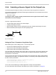
2.8 Input Lines
2.8.1 Voltage Requirements
:
Voltage Levels When the Standard I/O Cable is Used
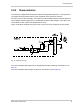
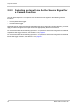
When a standard I/O cable is used, the following voltage requirements apply to the camera’s I/O
inputs (pins 3 and 4 of the 12-pin receptacle):
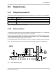
Voltage Levels When a PLC I/O Cable is Used
When a PLC I/O cable is used, the following voltage requirements apply to the inputs to the PLC
I/O cable. The PLC I/O cable will adjust the voltages to the levels required at the camera’s I/O input
(see the previous table).
Different voltage levels apply depending on whether you are using a standard I/O
cable or a PLC I/O cable (see below).
Voltage Significance
+0 to +24 VDC Recommended operating voltage.
+0 to +1.4 VDC The voltage indicates a logical 0.
> +1.4 to
+2.2 VDC
Region where the transition threshold occurs; the logical state is not defined in this region.
> +2.2 VDC The voltage indicates a logical 1.
+30.0 VDC Absolute maximum; the camera may be damaged if the absolute maximum is exceeded.
Table 5: Voltage Requirements for the I/O Input When Using the Standard I/O Cable
Voltage Significance
+0 to +24 VDC Recommended operating voltage.
+0 to +8.4 VDC The voltage indicates a logical 0.
> +8.4 to
+10.4 VDC
Region where the transition threshold occurs; the logical state is not defined in this region.
> +10.4 VDC The voltage indicates a logical 1.
+30.0 VDC Absolute maximum; the camera may be damaged if the absolute maximum is exceeded.
Table 6: Voltage Requirements for the I/O Input When Using a PLC I/O Cable