
User`s manual

Physical Interface
16 Basler aviator Camera Link
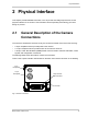
2.2 Camera Connector Pin Assignments
and Numbering
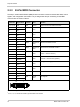
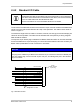
2.2.1 6-Pin Receptacle
The 6 pin receptacle is used to supply power to the camera. The pin assignments and pin
numbering for the receptacle are as shown in Table 2.
Pin Designation
1 +12 VDC Camera Power (+12 VDC ± 10%) *
2 +12 VDC Camera Power (+12 VDC ± 10%) *
3 Not Connected
4 Not Connected
5 DC Ground **
6 DC Ground **
Table 2: Pin Assignments and Numbering for the 6-pin Receptacle
* Pins 1 and 2 are tied together inside of the camera.
** Pins 5 and 6 are tied together inside of the camera.
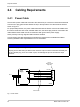
To avoid a voltage drop when there are long wires between your power supply and
the camera, we recommend that you provide +12 VDC through two separate wires
between the power supply and pins 1 and 2 in the receptacle. We also recommend
that you provide the ground through two separate wires between the power supply
and pins 5 and 6.
1
2
3
5
6
4