
User`s manual

Features
168 Basler aviator Camera Link
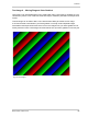
Test Image 3 - Moving Diagonal Gray Gradient (10 bit or 12 bit)
Test image 3 is a moving diagonal gray gradient test image similar to test image 2, but it is a 10 bit
pattern if the camera is set to output pixel data at 10 bit depth or a 12 bit pattern if the camera is set
to output pixel data at 12 bit depth. The image moves by one pixel from right to left whenever a new
image acquisition is initiated. The test pattern uses a counter that increments by one for each new
image acquisition.
The mathematical expression for this test image when the camera is set for 10 bit output is:
Gray Value = [column number + row number + counter] MOD 1024
The mathematical expression for this test image when the camera is set for 12 bit output is:
Gray Value = [column number + row number + counter] MOD 4096
Test Image 4 - Moving Diagonal Gray Gradient Feature Test (8 bit)
The basic appearance of test image 4 is similar to test image 2 (the 8 bit moving diagonal gray
gradient image). The difference between test image 4 and test image 2 is this: if a camera feature
that involves digital processing is enabled, test image 4 will show the effects of the feature while
test image 2 will not. This makes test image 4 useful for checking the effects of digital features such
as the luminance lookup table.
Test Image 5 - Moving Diagonal Gray Gradient Feature Test (10 bit or 12 bit)
The basic appearance of test image 5 is similar to test image 3 (the 10 or 12 bit moving diagonal
gray gradient image). The difference between test image 5 and test image 3 is this: if a camera
feature that involves digital processing is enabled, test image 5 will show the effects of the feature
while test image 3 will not. This makes test image 5 useful for checking the effects of digital
features such as the luminance lookup table