
User`s manual


Configuring the Camera
4-10
BASLER A102f
DRAFT
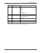
Control and Status Registers for Format_7, Mode_0
The base address for each Format_7, Mode_0 camera control register is:
Bus_ID, Node_ID, FFFF F1F0 0000
The offset field in the table is the byte offset from the above base address.
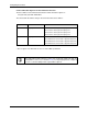
* The Raw 8 and Raw 16 Color_Coding_IDs are defined in version 1.31 of the IIDC specification.
Offset Name Notes
000h Max_Image_Size_Inq A102f: Hmax = 1392, Vmax = 1040
A102fc: Hmax = 1388, Vmax = 1038
004h
Unit_Size_Inq A102f: Hunit = 1, Vunit = 1
A102fc: Hunit = 2, Vunit = 2
008h
Image_Position Default = (0, 0)
00Ch
Image_Size Default = (Hmax, Vmax)
010h
Color_Coding_ID A102f default = Mono 8 (ID = 0)
A102fc default = YUV 4:2:2 (ID = 2)
014h
Color_Coding_Inq The A102f supports the following color codes in this
mode:
• Mono 8 (ID = 0)
• Mono 16 (ID = 5)
The A102fc supports the following color codes in
this mode:
• Mono 8 (ID = 0)
• Raw 8 * (ID = 9)
• Raw 16 * (ID = 10)
• YUV 4:2:2 (ID = 2)
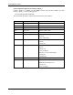
034h
Pixel_Number_Inq The value of this register depends on the following
registers:
• Image_Size
038h
Total _B yt es _Hi_ In q The value of this register depends on the following
registers:
• Image_Size
• Color_Coding_ID
The value covers the following data:
• Image data
• Padding bytes
03Ch
Total_Bytes_Lo_Inq See TOTAL_BYTES_HI_INQ register
040h
Packet_Para_Inq UnitBytePerPacket = 4
MaxBytePerPacket depends on:
• Image_Size
• Color_Coding_ID