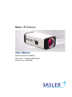
Basler IP Camera User’s Manual Document Number: AW000721 Version: 04 Language: 000 (English) Release Date: 8 April 2009
Contacting Basler Support Worldwide Europe: Basler AG An der Strusbek 60 - 62 22926 Ahrensburg Germany bc.support.ip@baslerweb.com Americas: Basler, Inc. 855 Springdale Drive, Suite 160 Exton, PA 19341 U.S.A. bc.support.ip@baslerweb.com Asia: Basler Asia Pte. Ltd 8 Boon Lay Way # 03 - 03 Tradehub 21 Singapore 609964 bc.support.ip@baslerweb.com www.basler-ipcam.com All material in this publication is subject to change without notice and is copyright Basler Vision Technologies.
Table of Contents Table of Contents 1 Introduction . . . . . . . . . . . . . . . . . . . . . . . . . . . . . . . . . . . . . . . . . . . . . . . . . . . . . 1 1.1 About this Document . . . . . . . . . . . . . . . . . . . . . . . . . . . . . . . . . . . . . . . . . . . . . . . . . . . 1 1.2 Precautions . . . . . . . . . . . . . . . . . . . . . . . . . . . . . . . . . . . . . . . . . . . . . . . . . . . . . . . . . . 1 1.3 Firmware Updates . . . . . . . . . . . . . . . . . . . . . . . . . . . . . . . .
Table of Contents ii Basler IP Camera
Introduction 1 Introduction 1.1 About this Document This document is intended for administrative users of the camera. Previous experience with networking will be a great help when using this document. This document assumes that you have already followed the instructions in the Installation Guide to install your camera. 1.2 Precautions CAUTION Electrical Shock Hazard Touching the camera’s internal components may result in an electrical shock. 1. Do not open the camera housing.
Introduction WEEE Directive The European Union has enacted Directive 2002/96/EC on Waste Electrical and Electronic Equipment (the WEEE Directive). This directive is only applicable in European Union member states. A WEEE symbol (see left) on this product or its documentation indicates that the product must not be disposed of with other waste. The product must be disposed of via an approved, environmentally safe recycling process.
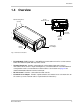
Introduction 1.4 Overview M3 Mounting Holes (8 total) RJ-45 Network / PoE Terminal Connector 1/4’’ Standard Tripod Mount DC Iris Control CS-mount Lens Adapter Fig. 1: Camera Connections RJ-45 Network / PoE - Provides a 10/100 Ethernet connection and can be used to connect Power over Ethernet (IEEE 802.3af) to the camera.
Introduction 4 Basler IP Camera
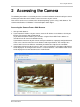
Accessing the Camera 2 Accessing the Camera The following instructions assume that you have used the Installation Guide to install your camera and that you know either the IP Address or the host name of your camera. Your camera can be accessed from most standard operating systems using a web browser. The recommended browser is Windows™ Internet Explorer 6.0 or higher. Accessing the Camera From a Web Browser 1. Start your web browser. 2.
Accessing the Camera 6 Basler IP Camera
Configuring the Camera 3 Configuring the Camera This section describes how to configure your camera. It is intended to be used by Administrators who have full access rights to the camera. 3.1 Introduction When adjusting the parameters used to configure the camera, it helps to have an overview of the camera’s functionality in mind. Figure 2 on page 9 shows a block diagram of the camera outlining the basic functional units in the camera and shows how they are related.
Configuring the Camera streaming images. When you use the web client to open any parameter group (except the Streaming group) and you adjust a parameter, you will find that the camera captures and streams images normally. The parameters in the Streaming group can only be adjusted when the camera is in "configuration" mode, and when the camera is in configuration mode, it can not stream images.
Configuring the Camera Network Parameters Camera Web Server Microprocessor Stream 0 Parameters Stream 0 Encoder Alarm Parameters Image Control Parameters Imaging Sensor Motion Detection Parameters I/O Parameters Control and Processing System Parameters MJPEG, MPEG 4 or H.
Configuring the Camera 3.2 Accessing the Configuration Tools and Camera Parameters 1. If you have not already done so, start your web browser and access the Basler Surveillance Web Client in your camera as described in Section 2 on page 5. 2. When the Basler Surveillance Web Client opens as shown below, click the Configuration button on the left side of the Basler tool bar.
Configuring the Camera 3. A Camera Configuration menu will open on the left side of the client as shown below. Notice that the parameters used to configure the camera appear in groups such as the Image Controls group and the Streaming group. You can open a parameter group by clicking the + sign beside the group name. By default, the camera is set so that video stream 0 is an MJPEG stream, and a Live Stream 0 tab will appear in the client as shown above. A live video stream will appear in the tab.
Configuring the Camera 3.3 Image Control Parameters The parameters in the Image Controls group control the quality of the images captured by the camera's imaging sensor. 3.3.1 Auto Tab Exposure Mode - Sets the camera’s exposure mode. Normal = The camera will automatically adjust exposure time and gain to maintain good overall image quality as lighting conditions change.
Configuring the Camera Backlight Compensation - Check the box to enable the camera’s backlight compensation feature. This feature automatically compensates when the main lighting comes from behind the image subject. White Balance Mode - Sets the camera’s automatic white balance mode. Auto = The camera will automatically adjust the white balance and the white balance adjustments will be continuously updated as lighting conditions change. The white balance control will assume average lighting conditions.
Configuring the Camera IR Filter Mode - Sets the mode of operation for the camera’s IR-cut filter. (This setting is only available on day/night cameras.) Auto = The camera automatically senses the change from night to day or from day to night and sets the position of the camera’s IR-cut filter accordingly. Open = The IR-cut filter is moved to the open position and kept there. Closed = The IR-cut filter is moved to the closed position and kept there.
Configuring the Camera 3.4 Streaming Parameters The parameters in the Streaming group are used to control the characteristics of the image area that will be captured by the camera’s sensor. They are also used to control the characteristics of the video streams that are output from the camera. The camera can produce up to three individually configured video streams. The streams are designated as stream 0, stream 1, and stream 2. Stream 0 is always enabled. Streams 1 and 2 can be either enabled or disabled.
Configuring the Camera 3.4.1 Global Tab The parameters on the Global tab control the way that the camera’s imaging sensor will capture images. Because the images captured by the sensor are used for all three video streams, the parameters on this tab are considered to be "global", i.e., changes made here will affect what you can do when you work with the individual stream parameters. Some of the parameters in this group are used to set the imaging sensor’s "area of interest" (AOI).
Configuring the Camera Frame Rate Mode - Sets the rate at which the camera’s sensor will capture frames (images). For example, selecting 15 FPS means that the camera’s imaging sensor will capture 15 frames per second. Note that on some camera models, typically those with large imaging sensors, the maximum rate at which the sensor can capture images (i.e., the frame rate) is limited.
Configuring the Camera Sensor AOI Editor - Whenever the Global tab is selected, a sensor AOI Editor screen will also be available as shown below. You can use the editor to set the sensor AOI size and position rather than setting numbers in the boxes on the Global tab. To set the sensor AOI with the editor, simply use your cursor to drag the edges of the red rectangle that represents the sensor AOI.
Configuring the Camera Image Rotation - Sets the degrees of rotation for the images captured by the sensor. 0° = Don’t rotate the images. 180° = Rotate the images 180 degrees. Test Image Mode - Enables or disables the camera’s test image feature. When one of the test image modes is enabled, the camera will generate test images using it’s digital devices rather than the imaging sensor. The generated test images will be transmitted on all enabled streams.
Configuring the Camera White Balance Mask Click the White Balance Mask button to open the White Balance Mask Editor as shown below. The white balance mask selects the area(s) of the image that will be used by the camera’s automatic white balancing function when the White Balance Mode parameter is set to Auto (see Section 3.3 on page 12). Highlighted areas in the editor will be included in the white balance mask and unhighlighted areas will not.
Configuring the Camera Auto-Brightness Mask Click the Auto-Brightness Mask button to open the Auto Brightness Mask Editor as shown below. The auto brightness mask defines the area(s) of the image that will be used by the camera when it performs automatic exposure, gain, and iris control (see Section 3.3 on page 12). Highlighted areas in the editor will be included in the auto-brightness mask and unhighlighted areas will not.
Configuring the Camera Privacy Mask Click the Privacy Mask button to open the Privacy Mask Editor as shown below. The privacy mask defines the area(s) of the image that will be blacked out in the images in the video streams. Highlighted areas in the editor will be included in the privacy mask and will be blacked out. Unhighlighted areas will not. To highlight an area within the editor, simply left click your mouse and drag the cursor over the editor screen.
Configuring the Camera Motion Mask Click the Motion Mask button to open the Motion Mask Editor as shown below. The motion mask defines the area(s) of the image that will be used for the camera’s motion detection function (see Section 3.5 on page 32). Highlighted areas in the editor will be included in the motion detection mask and used for motion detection. Unhighlighted areas will not. To highlight an area within the editor, simply left click your mouse and drag the cursor over the editor screen.
Configuring the Camera 3.4.2 Stream Tabs The parameters on the Stream 0 Tab, Stream 1 Tab, and Stream 2 Tab, control the way that the video stream associated with the selected tab is configured. Some of the parameters on each stream tab are used to set the "area of interest" (AOI) for the video stream controlled by the tab.
Configuring the Camera Encoder Type - Sets the encoder type for the stream controlled by the currently selected tab. Off = The video stream is disabled and no images will be streamed. This setting is only available on the Stream 1 and Stream 2 tabs. Stream 0 is always enabled, and the off setting is not available for this stream. JPEG = The camera will use motion JPEG (MJPEG) encoding for the images streamed. The motion JPEG format uses standard JPEG still images to create the video stream.
Configuring the Camera Quality - If the Encoder Mode parameter is set to VBR, then the Quality parameter will determine the quality level of the images in the stream controlled by the currently selected tab. A higher setting means better quality. Using higher quality settings will reduce the rate at which the camera can encode and stream images. Using lower quality settings will increase the rate. Note that the effect of the quality setting is not precisely equivalent for each encoder type.
Configuring the Camera Stream AOI Left - As shown in Figure 4 on page 24, sets the left offset (in pixels) for the stream AOI, i.e., how far the stream AOI will be offset from the left edge of the image area captured by the camera’s sensor. The setting must be a multiple of 2. See also, the stream AOI Editor description on the next page. Stream AOI Top - As shown in Figure 4 on page 24, sets the top offset (in pixels) for the stream AOI, i.e.
Configuring the Camera Stream AOI Editor - Whenever a stream tab is selected, an AOI Editor screen will also be available as shown below. Rather than setting numbers in the boxes on the stream tab, you can use the editor to set the AOI size and position for the stream controlled by the currently selected tab. To set the stream AOI with the editor, simply use your cursor to drag the edges of the red rectangle that represents the stream AOI.
Configuring the Camera Output Scaling - Sets the amount that captured images will be rescaled before they are encoded and transmitted in the stream controlled by the currently selected tab. 1:1 = No rescaling. 1:2 = Rescale to 1/2 size. 1:4 = Rescale to 1/4 size. 1:8 = Rescale to 1/8 size. Note that increasing the level of output scaling will decrease the workload on the processor in the camera. For more information about the effects of processor workload, see Section 3.1 on page 7.
Configuring the Camera Text Overlay Click the Text Overlay button to open the text overlay dialog box as shown below. The dialog box lets you define the text that will appear in a bar at the top or the bottom of each image transmitted in the stream controlled by the currently selected tab. Overlay Text - Sets the text that will appear in the text overlay bar.
Configuring the Camera Overlay Position - Sets the position of the text overlay bar. Top = Place the text overlay bar at the top of each streamed image. Bottom = Place the text bar at the bottom of each image. Remove Text Click the Remove Text button to clear all of the text from the Overlay Text line. +Date Click the + Date button to quickly enter the $date$ expression into the Overlay Text line.
Configuring the Camera 3.5 Motion Detection Parameters The parameters in the Motion Detection group are used to control the operation of the camera’s motion detection function. To understand what the parameters in this group do, you should have a basic idea about how motion detection works: Just before the camera captures a new image, it takes the last few captured images (from its memory) and uses them to create an averaged image called a "history image".
Configuring the Camera Motion Threshold - Sets a threshold for motion detection. If the number of changed pixels in the current image is above the motion threshold and below the motion limit (see the next parameter), then motion will be detected. Motion Limit - Sets a limit for motion detection. If the number of changed pixels in the current image is above the motion threshold (see the previous parameter) and below the motion limit, then motion will be detected.
Configuring the Camera 3.6 Alarm Handling Parameters The parameters in the Alarm Handling group are used to select the sources that can declare an alarm condition and to control the actions that will be taken when an alarm condition is declared. 3.6.1 Alarm Sources Section The alarm sources section of the alarm handling parameters group is used to select the sources that can declare an alarm condition.
Configuring the Camera 3.6.2 Alarm Buffers Section Each video stream can have an alarm buffer. Normally, the alarm buffer on a stream is a simply a first-in-first-out buffer that stores the last N captured images for the stream (N depends on the size of the images being encoded and the size of the buffer). If an alarm condition is declared, the alarm buffer will only continue to buffer images after the alarm is declared until the part of the buffer that is allocated for post alarm image storage is full.
Configuring the Camera 3.6.3 Alarm Actions Section The alarm actions section of the alarm handling parameters is used to control the actions that will be taken when an alarm condition is declared. Digital Output Tab Action Enable - Check the Action Enable box on the Digital Output tab to enable the camera’s digital output line as an action to take when an alarm condition is declared. If the digital output line is enabled as alarm action, it will become active when an alarm condition is declared.
Configuring the Camera HTTP Tab Action Enable - Check the Action Enable box on the HTTP tab to enable the sending of an HTTP request as an action to take when an alarm condition is declared. HTTP URL - Enter a valid URL request. You could, for example, enter this request: http://MyServer/cgi-bin/alarm.
Configuring the Camera 3.7 Network Parameters The parameters in the Network group are used to set the camera’s IP configuration. 3.7.1 Settings Tab Host Name - Assigns a host name to the camera. Only letters, digits, and dashes are allowed. No spaces or periods are allowed. (If DHCP addressing is enabled, the host name may be overwritten by the DHCP server.) DHCP - Check the DHCP box to enable camera IP addressing via a DHCP server.
Configuring the Camera 3.7.2 RTSP Streaming Tab Enabled - Check the Enabled box to enable the Real Time Streaming Protocol (RTSP). RTSP is a control protocol that allows the camera to negotiate which transport protocol to use for the video streams. Typically, RTSP streaming should be enabled. RTSP Port - Sets the port that will be used by RTSP. The default port is 554. Multicast - Check the Multicast box to enable multicast streaming. Multicasting is a bandwidth conserving technology.
Configuring the Camera 3.8 Input / Output Parameters The parameters in the Input/Output group are used to work with the camera’s digital input and output pins and to configure the camera’s RS-232 serial port. 3.8.1 Digital I/O Tab IR Filter Announce Mode - Sets the mode for the camera’s IR-cut filter announce feature. (This setting is only available on day/night cameras.) Off = The announce feature is off.
Configuring the Camera 3.8.2 Serial I/O Tab Forwarding - Check the Forwarding box to enable serial port forwarding. When forwarding is enabled, serial commands issued via TCP/IP over the designated port (see the Port parameter below) will be forwarded to the serial port. Baud Rate - Sets the baud rate for the serial port (in bits per second). Line Configuration - Sets the line configuration for the serial port in Data Bits, Parity, Stop Bit format.
Configuring the Camera 3.9 User Parameters The parameters in the User group are used to manage user authentication on the camera. 3.9.1 Enabling Authentication and Logging in for the First Time Authentication enabled - Check the Authentication enabled box to enable user authentication on the camera. With user authentication enabled, a valid user name and password will be required to access the camera.
Configuring the Camera 3.9.2 Logging Out and Logging In Once you have logged into the camera, a Logged in: indicator, a Change Password button, and a Logout button (shown circled in red below) will appear in the Basler tool bar. Notice that the Logged in: indicator displays the user name of the person who is currently logged into the camera (in this case, the user is named "admin"). Click the Change Password button to change the password of the person who is currently logged into the computer.
Configuring the Camera 3.9.3 Managing Users To manage users, you must be logged into the camera as an administrator. Once you are logged in, access the User parameters group, and click on the Manage Users button. A Manage Users tab will appear as shown below. User names can include letters, numbers, and underscores (_). User names and passwords are case sensitive. The available user levels are described in Table 1. User Level Meaning Administrator Can change all camera configuration parameters.
Configuring the Camera To Add a New User 1. Click the New User button on the Manage Users tab. A User Editor window will appear as shown below. 2. Enter a user name, select a user level (see Section Table 1: on page 44), enter a password, enter the password verification, and click the Save button. 3. A Success message window will open. Click the OK button. To Delete an Existing User 1. In the Manage Users tab, click on the name of the user you wish to delete.
Configuring the Camera To Change an Existing User’s Password 1. In the Manage Users tab, click on the name of the user whose password you wish to change. As shown below, the user information will become highlighted, and the Change Password button will become ungrayed. 2. Click the Change Password button. A User Editor window will appear as shown below. 3. Enter a new password, reenter the password to verify, and click the Save button.
Configuring the Camera To Change an Existing User’s User Level 1. In the Manage Users tab, click on the name of the user whose user level you wish to change (see Section Table 1: on page 44 for user level descriptions). As shown below, the user information will become highlighted, and the Change User-Level button will become ungrayed. 2. Click the Change User-Level button. A User Editor window will appear as shown below. 3. Select a new user level from the drop down menu, and click the Save button.
Configuring the Camera 3.10 System Parameters The parameters in the System group provide some basic information about the camera and allow you to set basic system characteristics such as the date and time. 3.10.1 Info Tab Manufacturer Name - Indicates the name of the camera’s manufacturer. Model Name - Indicates the camera’s model name. Firmware Version - Indicates the version number of the firmware currently installed in the camera. Serial Number - Indicates the camera’s serial number.
Configuring the Camera $I = display the hour as a decimal number using a 12-hour clock (i.e., from 01 to 12). $m = display the month as a decimal number (i.e., from 01 to 12). $M = display the minute as a decimal number. $r = display the time in a.m. and p.m. notation. $R = display the time in 24 hour notation. $S = display the seconds as a decimal number. $T = display the current time, same as entering $H:$M:$S. $y = display the year without the century as a decimal number.
Configuring the Camera Time Zone Code Location UTC-0 London, England IRT-4:30IRST-4:30 Tehran, Iran IST-5:30 New Delhi, India ICT-7 Jakarta, Indonesia CST-8 Beijing, China JST-9 Tokyo, Japan AWST-8AWDT-9,M10.5.0,M3.5.0/03:00:00 Perth, Australia ACST-9:30ACDT-10:30,M10.5.0/02:00:00,M4.1.0/03:00:00 Adelaide, Australia ACST-9:30 Darwin, Australia AEST-10AEDT-11,M10.1.0/02:00:00,M4.1.0/03:00:00 Hobart, Australia AEST-10 Brisbane, Australia NZST-12NZDT-13,M10.1.0/02:00:00,M3.3.
Configuring the Camera 3.10.3 Management Tab Show System Log Click the Show System Log button to display a log of system messages. Restart the Camera Click the Restart the Camera button to reboot the camera. When the reboot is complete, the web client will reopen in your browser. Restarting your camera will not change any parameter settings Reset to Factory Defaults Click the Reset to Factory Defaults button to reset the camera to factory defaults.
Configuring the Camera 3. A File Download window will open as shown below. Click the Save button in the dialog box. 4. A Save As dialog box will open as shown below. Select a location where the file will be saved, enter a file name (we recommend using .cfg as the file name extension), and click the Save button. 5. When the Download Complete screen appears, click the Close button. 6. Click the Close button in the Configuration Management dialog box.
Configuring the Camera To upload a saved configuration file on your PC to the camera, follow the steps below. When you upload the file, the parameters in the uploaded file will overwrite the current parameter settings in the camera. 1. Click the Config Management button. 2. A Configuration Management dialog box will open as shown below. Click the Browse button in the dialog box. 3. A Choose File dialog box will open as shown below.
Configuring the Camera Start Firmware Update Occasionally, firmware updates may be made available to the field. The Start Firmware Update button is used to start the firmware update process. To determine the version of the firmware currently in your camera, access the Info tab (see page 48). To see if a new firmware version is available, go to our website: www.basler-ipcam.com If newer firmware is available, download it to your computer.
Configuring the Camera 3. A Choose File dialog box will open as shown below. Navigate to the location of the downloaded firmware file, select the file, and click the Open button. 4. Click the Upload button on the Firmware Upload dialog box. A message will appear indicating that the firmware is being uploaded from your PC to your camera. 5.
Configuring the Camera 6. Click the Yes button in the Are you sure? message window to start the update or the No button to cancel the update. 7. If you clicked the Yes button a message will appear indicating that the firmware update is in progress. 8. Once the update is complete, the camera will reboot and the web client will reopen in your browser. If your browser times out during the update process, press the Ctrl and F5 keys (at the same time) to refresh the browser.
The Terminal Connector 4 The Terminal Connector The 6-pin terminal connector on the back of the camera can be used to: provide power to the camera (when PoE is not used). access the camera’s input line. access the camera’s output line. access the camera’s RS-232 connection. The terminal connector on the camera is a Phoenix header (part number 1881480). The recommended mating connector is a 6-pin Phoenix plug (part number 1881367). A Phoenix plug of this type is included with each camera.
The Terminal Connector The pin numbering for the terminal connector on the camera is as shown below. 1 2 3 4 5 6 Fig. 5: Terminal Connector Pin Numbering The pinout for the terminal connector is as described in Table 3. Pin Function Description 1 Ground Ground (for camera power, for the I/O signals, and for the RS-232 serial port) 2 Camera Power Use this connection to supply power to the camera (if you are not supplying camera power via PoE).
The Terminal Connector Pin 4 Function Description Output The output employs an open collector transistor connected to ground as shown in Figure 6 on page 60. As shown below, the output will or will not be connected to ground via the transistor depending on the state of the output and whether the output is set for the normal or the inverted mode. See Section 3.8.1 on page 40 for more information about setting the output mode.
The Terminal Connector Camera Gnd 1 Camera Power 2 Input 3 +7 to +20 VDC Switch +24 VDC Max Output 4 Device Relay RS-232 Tx 5 RS-232 Rx 6 RS-232 Gnd RS-232 Rx RS-232 Tx Fig.
The Terminal Connector Camera Gnd Camera Power Input 1 +7 to +20 VDC 2 3 Device (applies 0 to + 24 VDC max) Output +24 VDC Max 4 Device Relay RS-232 Tx 5 RS-232 Rx 6 RS-232 Gnd RS-232 Rx RS-232 Tx Fig.
The Terminal Connector 62 Basler IP Camera
Day/Night Functionary 5 Day/Night Functionary 5.1 Introduction IP Cameras with the letters "dn" at the end of the model name (e.g., BIP-640c-dn) are equipped with day/night functionality. Cameras with day/night functionality are well-suited for use in areas with natural lighting during the day and artificial lighting at night.
Day/Night Functionary IR-Cut Filter Modes of Operation The IR-cut filter mechanism in the camera has several modes of operation: In Auto mode, the camera automatically senses the change from night to day or from day to night. When a night-to day change is detected, the camera will automatically move the filter to the closed position. And when a day-to-night change is detected, the camera will automatically move the filter to the open position.
Day/Night Functionary 5.2 IR-Cut Filter Control Options Controlling the IR-Cut Filter Position Via Input Pin 0 As mentioned in Section 5.1 on page 63, the IR-cut filter can be set for several different modes of operation. If you set the IR-cut filter mode to "Input Pin 0 Controlled" this will let you control the position of the IR-cut filter (open or closed), by inputting a signal into input pin 0 on the camera. When the input is active, the filter will be placed in the open position.
Day/Night Functionary Controlling an External Device Based on the IR-Cut Filter Position As mentioned in Section 5.1 on page 63, the camera includes a feature called the IR-cut filter announce mode. When this feature is enabled, the camera will announce the current position of the IR-cut filter by setting the state of output pin 0. When the IR-cut filter is in the open position, output pin 0 will be set to active. And when the IR-cut filter is in the closed position, output pin 0 will be set to inactive.
Technical Specifications 6 Technical Specifications 6.1 BIP-640c and BIP1000c Specifications Specification BIP-640c BIP-640c-dn BIP-1000c BIP-1000c-dn Sensor Sony ICX424 1/3" progressive scan color CCD Sony ICX204 1/3" progressive scan color CCD Effective Pixels 640 (H) x 480 (V) 1024 (H) x 768 (V) Pixel Size 7.4 µm x 7.4 µm 4.65 µm x 4.65 µm MJPEG MPEG-4 H.
Technical Specifications Specification Alarm Management BIP-640c BIP-640c-dn BIP-1000c BIP-1000c-dn Ring buffer for pre and post alarm Events triggered by motion detection or external input Image upload via FTP or Email Protocols TCP/IP, HTTP, UDP, ICMP, ARP, DHCP, NTP, RTP, RTSP, RTCP, SMTP, IGMP, UpnP Processor / Memory 600 MHz dual core multimedia DSP, FPGA 128 MB RAM, 8 MB Flash Battery backed-up real time clock Minimum PC Requirements Pentium 4, 2.
Technical Specifications 6.2 BIP-1300c and BIP-1600c Specifications Specification BIP-1300c Sensor Sony ICX445 1/3" progressive scan color CCD Sony ICX274 1/1.8" progressive scan color CCD Effective Pixels 1280 (H) x 960 (V) 1600 (H) x 1200 (V) Pixel Size 3.75 µm x 3.75 µm 4.4 µm x 4.4 µm Frame Rate Full resolution: D1 (720 x 480): Minimum Illumination BIP-1300c-dn BIP-1600c MJPEG MPEG-4 H.264 MJPEG MPEG-4 H.
Technical Specifications Specification BIP-1300c BIP-1300c-dn BIP-1600c Minimum PC Requirements Pentium 4, 2.4 GHz or higher, 256 MB RAM or more AGP Graphics card, 64 MB RAM or more 1280 x 1024 display or better 100 Mbps NIC Win 2k, XP, Vista, or Server 2003 OS Internet Explorer 6.0 or higher Power PoE (Power over Ethernet IEEE 802.
Technical Specifications 6.3 Stress Test Results Basler IP Cameras were submitted to an independent mechanical testing laboratory and subjected to the stress tests listed below. After mechanical testing, the cameras produced normal images during standard operational testing. Test Standard Conditions Vibration (sinusoidal, each axis) DIN EN 60068-2-6 10-58 Hz / 1.
Technical Specifications 72 Basler IP Camera
Software License Information Appendix A Software License Information MPEG-4: THIS PRODUCT IS LICENSED UNDER THE MPEG-4 VISUAL PATENT PORTFOLIO LICENSE FOR THE PERSONAL AND NON-COMMERCIAL USE OF A CONSUMER FOR (i) ENCODING VIDEO IN COMPLIANCE WITH THE MPEG-4 VISUAL STANDARD ("MPEG-4 VIDEO") AND/OR (ii) DECODING MPEG-4 VIDEO THAT WAS ENCODED BY A CONSUMER ENGAGED IN A PERSONAL AND NONCOMMERCIAL ACTIVITY AND/OR WAS OBTAINED FROM A VIDEO PROVIDER LICENSED BY MPEG LA TO PROVIDE MPEG-4 VIDEO.
Software License Information Other Software The camera contains software originating from a variety of third parties. To view the software license information: 1. Start the Surveillance Web Client as described in Section 2 on page 5. 2. Click the About tab as shown below. 3. Click the Copyright link as shown below. A page containing license information will appear.
Revision History Revision History Doc. ID Number Date Changes AW00072101000 30 Jul 2008 Initial release of this document. AW00072102000 19 Dec 2008 Added Section 1.3 on page 2 pointing out the availability of firmware updates. Updated the web browser recommendation and the procedure for accessing the camera in Section 2 on page 5. Added the Sharpness parameter description to Section 3.3.1 on page 12. Added the Auto (limited) selection to the White Balance Mode parameter description in Section 3.3.
Revision History Doc. ID Number Date AW00072103000 24 Mar 2009 Changes Added the WEEE information to page 2. Updated the description on page 11 of the Refresh Rate and added a description of the Plugin Help button. Updated the description on page 12 of the Manual setting for the Exposure Mode parameter. Added descriptions of the new Shutter Mode and Gain Mode parameters to page 14. Expanded the notes about the configuration mode that appear on page 15.
Feedback Feedback Your feedback will help us improve our documentation. Please click the link below to access an online feedback form. Your input is greatly appreciated. http://www.baslerweb.com/umfrage/survey.
Feedback 78 Basler IP Camera
Index Index A E adding a user............................................45 alarm actions ............................................36 alarm buffer size parameter .....................29 alarm buffer state parameter ....................35 alarm buffers ............................................35 alarm handling parameters.......................34 alarm off delay milliseconds parameter....33 alarm on delay milliseconds parameter....33 alarm sources...........................................
Index I image controls parameters ......................12 image rotation parameter .........................19 include image parameter ...................36, 37 info tab .....................................................48 input pin ...................................................58 input pin mode parameter ........................40 input pin parameter .................................. 40 input/output parameters ...........................40 IP address parameter ..............................
Index S saturation parameter ................................12 saving parameter settings ........................51 sensitivity parameter ................................32 sensor AOI ...............................................16 sensor AOI editor .....................................18 sensor AOI height parameter ...................17 sensor AOI left parameter ........................17 sensor AOI top parameter ........................17 sensor AOI width parameter.....................
Index 82 Basler IP Camera