
Datasheet


(c) 2020 Basicmicro. All Rights Reserved.
RoboClaw 120A/160A/200A Dual Channel Motor Controller Data Sheet
Control Interface (CTRL)
RoboClaw 120A, 160A and 200A use Molex style female connectors. The following tables list the pins and their available
functions. All pins are 5V tolerant and output 3.3V for compatibility with processor such as Rasberry Pi and Arduino.
CTRL1 and CTRL2 pins are low side drivers at 40VDC, 3A per output. R/C pulse input, Analog and TTL can be generated
from any microcontroller such as a Arduino or Rasberry Pi. The R/C Pulse in pins can also be driven by any standard
R/C radio receiver. There are several user congurable options depending on the device used to control RoboClaw. To
congure RoboClaw, install Motion Studio and connect it to an available USB port.
Pin NAME UART TTL ANALOG R/C PULSE
FLIP
SWITCH
E-STOP HOME V-CLAMP
1 LB+
2 S4 X(3) Motor 1 (2) X(1)
3 5V+
4 S3 X(5) X(3) X(1)
5 GND
6 S2 TX X(4) X(4)
7 S5 X(3) Motor 2 (2) X(1)
8 S1 RX X(4) X(4)
Notes:
1. Control external voltage clamp circuit. Redirect the regenerative function of RoboClaw.
2. Input can be used for home switch and automatic homing on power up.
3. Optional E-Stop input conguration. Pin state changes error will clear or board reset required.
4. Supports mixed control or individual control of motor channel.
5. Supports TTL or R/C signals
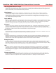
USB
CTRL
DRV
ERR
STAT1
STAT2
ENC
Mating Connector Part
Number: 794617-8
2 4 6 8
1 3 5 7