
Datasheet


RoboClaw ST 2x45A Dual Channel Motor Controller Data Sheet
(c) 2020 Basicmicro. All Rights Reserved.
Logic Battery (LB IN)
The logic circuit of RoboClaw can be powered from a secondary battery wired to LB IN. A logic battery will prevent
brownouts when the main battery is low or under heavy load. The positive (+) terminal is located at the board edge and
ground (-) is the inside pin closest to the heatsink.
Encoder Inputs (1A / 1B / 2A / 2B)
The encoders inputs are labeled 1B, 1A, 2B and 2A. 1B and 1A are the inputs for encoder 1. 2B and 2A are the inputs
for encoder 2 which also correspond to motor channel 1 and motor channel 2. Quadrature encoder inputs are typically
labeled 1A, 1B, 2A and 2B. Quadrature encoders are directional. When connecting encoders make sure the leading
channel for the direction of rotation is connected to A. If one encoder is backwards to the other you will have one internal
counter counting up and the other counting down. Use Motion Studio to determine the encoders direction relative to
the motors rotation. Encoder channels A and B can be swapped in software using Motion Studio to avoid re-wiring the
encoder or motor.
Control Inputs (S1 / S2 / S3 / S4 /S5)
S1, S2, S3, S4 and S5 are congured for standard servo style headers I/O (except on ST models), +5V and GND. S1 and
S2 are the control inputs for serial, analog and RC modes. S3 can be used as a ip switch input, when in RC or Analog
modes. In serial mode S3, S4 and S5 can be used as emergency stops inputs or as voltage clamping control outputs.
When congured as E-Stop inputs, they are active when pulled low. All I/O have internal pull-ups to prevent accidental
triggers when left oating. S4 and S5 can be congured as home switch and limit switch inputs. The pins closest to the
board edge are the I/0s, center pin is the +5V and the inside pins are ground. Some RC receivers have their own supply
and will conict with the RoboClaw’s 5v logic supply. It may be necessary to remove the +5V pin from the RC receivers
cable in those situations.
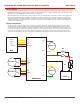
Cooling Fan Control
The cooling fan control will automatically turn on and o a fan based on RoboClaws temperature. The fan will turn on
when the board temperature reaches 45°C and will automatically turn o when the board temperature falls below 35°C.
The fan control circuit can power a 5VDC fan at up to 230mA. A wide range of fans can be used. The CFM rating of the
fan will determine how eective the fan is at cooling. A tested fan is available from DigiKey under part number:
259-1577-ND. However any fan can be used provided it meets the electrical specications outlined above.