
Instructions
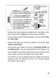

• If necessary, connect to the wires “Lock Relay COM” and
“Lock Relay NO” an additional doorbell. The wire coming
from the bell must be connected to the grey cable and the wire
coming from the power supply must be connected to the white
cable.
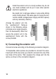
The exterior unit features a potential-free relay for an addition-
al bell with a load capacity of max. 36 V (AC/DC) and max. 3 A.
When the bell push button is pressed, the relay will close also.
The relay contact is potential-free, therefore both
DC voltage and AC voltage can be connected here
to operate the extra bell.
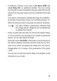
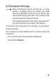
• Finally, we also have the option to connect the network adapt-
er. This of course is only necessary if you intend to operate the
exterior unit via LAN instead of WLAN.
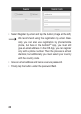
Insert the 4 wires “Net RF45” of the exterior unit into the pins of
the network adapters as follows and then close the tiny trans-
parent cover, which will squeeze the cables onto the contacts.
Orange/white = Pin1; orange = Pin2; green/white = Pin3; green
= Pin6
You can now connect the network cable to the adapter as the
connection to your router.
17