Model: BLMC1500 1,500 lb. (680 kg ) Motorcycle/ATV Lift READ the Manual Thoroughly Before Installing, Operating, Servicing, or Maintaining the Lift SAVE this MANUAL and ALL INSTRUCTIONS 1601 J.P. Hennessy Drive La Vergne, TN 37086 Tel.
Lift Purchase Buyers Agreement Warranty Each product comes with a two (2) year parts warranty with five (5) years warranty on the structure. The parts warranty is limited to defects in workmanship and material. The warranty does not cover misuse, abuse, overloading, lack of maintenance, and inappropriate use or “normal wear and tear”. Warranty parts must be returned to manufacturer for inspection to qualify for warranty. Shipping costs are the owner’s responsibility.
IMPORTANT: It is the shop owner's responsibility to provide a satisfactory installation area for the lift. Lifts should only be installed indoors on level concrete floors with a minimum of 4 inches (102mm) and 3000 psi (20.7MPa) concrete that has been aged a minimum of 30 days. Please consult a qualified individual if any doubt exists concerning proper installation and subsequent safe operation of the lift. Do not install the lift on asphalt or outdoors.
IMPORTANT SAFETY INSTRUCTIONS When using your garage equipment, basic safety precautions should always be followed, including the following: 1. Read all instructions 2. Do not operate equipment with a damaged cord or if equipment has been dropped or damaged – until it has been examined by a qualified service person 3. To reduce risk of fire, do not operate equipment in the vicinity of open containers of flammable liquids (gasoline) 4.
SPECIFICATIONS: Model Capacity Operating Pressure Lowered Height Raised Height Platform (L x W) (with extension) Shipping weight (with extension) LSSMC1500 1500lbs (680Kg ) 0.8-1.
ASSEMBLY: (1) Open the carton. Remove lift. (2) Connect the hose from the cylinder to the air-hydraulic pump. (3) Connect the compressed air (Max 100 psi) supply to the air-hydraulic pump. (4) Press the pedal of the air-hydraulic pump to raise up the lift. (5) Put on the front wheel vise and then tighten all the bolts and nuts. (Optional) (6) Put on the side extensions with rods and securing pins. Remember to insert the balance bar.
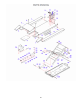
ITEM 1 2 3 4 5 6 7 8 9 10 11 12 13 14 15 16 17 18 19 20 21 22 23 24 25 26 28 29 30 31 32 33 34 35 36 37 38 39 40 41 42 43 44 45 46 47 48 49 50 51 DESCRIPTION Small ramp(Right) Connecting shaft Small platform assy Small ramp(Left) Ramp Support shaft assy Side extension(Left) Position pin Thread shaft assy Hex bolt Fixed plate assy(1) Fixed plate assy(2) Flat washer Limit shaft Platform assy Tool box Side extension(Right) Hex nut Spindle(1) Elastic washer Frame assy(1) Safety assy Elastic spindle Magnet Hex