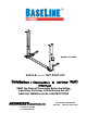
Model: BL209BP 9,000 LB (4091KG) TWO POST LIFT READ the Manual Thoroughly Before Installing, Operating, Servicing, or Maintaining the Lift SAVE this MANUAL and ALL INSTRUCTIONS Part Number: M-BL209-BP 1601 J.P. Hennessy Drive La Vergne, TN 37086 Tel.
Lift Purchase Buyers Agreement Warranty Each product comes with a two (2) year parts warranty with five (5) years warranty on the structure. The parts warranty is limited to defects in workmanship and material. The warranty does not cover misuse, abuse, overloading, lack of maintenance, and inappropriate use or “normal wear and tear”. Warranty parts must be returned to manufacturer for inspection to qualify for warranty. Shipping costs are the owner’s responsibility.
Your new lift will provide years of dependable service if installed, operated and maintained properly. Read and follow all safety, installation, operation, and maintenance instructions in this manual before installing and operating the lift. In addition, read and follow all safety and other information included on and with the lift before operating the lift. Keep this manual in a secure place for future reference, training and service part identification.
UNLOADING PROCEDURE and LIFT PACKAGE CONTENTS For your information: All lift components are grouped together in one package held at each end by steel frames. Unpacking Procedure: When the lift arrives on site: If possible have the lift unloaded in the installation area. Check for freight damage and report immediately to the trucking company who delivered the lift. Check for missing parts and report immediately to the factory.
IMPORTANT SAFETY INSTRUCTIONS When using your garage equipment, basic safety precautions should always be followed, including the following: 1. Read all instructions 2. Do not operate equipment with a damaged cord or if equipment has been dropped or damaged – until it has been examined by a qualified service person 3. To reduce risk of fire, do not operate equipment in the vicinity of open containers of flammable liquids (gasoline) 4.
7. Important: Removal or installation of heavier parts can change the vehicle's center of gravity on the lift resulting in a critical load shift. The vehicle may then be unstable. Plan ahead for this possibility to insure continued safety and refer to the vehicle manufacturer’s service manual for recommended procedures. 8. Always keep the lift area free of obstructions and debris. Clean up grease and oil spills immediately. 9. Never raise a vehicle with passengers inside.
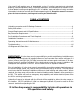
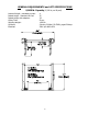
GENERAL REQUIREMENTS and LIFT SPECIFICATIONS 9,000 lb. Capacity (2,250 lb. per lift pad) Lowered Height - Standard Lift Pad: Raised Height - Standard Lift Pad: Raised Height with adapters: Lifting Time: Shipping Weight: Concrete: Electrical: 4’’ 71’’ 74’’ 50 sec 1,298 lb 4 inches, 3000psi (20.7MPa), aged 30 days.
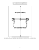
BAY DIMENSION REQUIREMENT EACH BASEPLATE MUST MAINTAIN A MIN.
TOOLS REQUIRED and PRE INSTALLATION PROCEDURES Tools Required: Gather all the tools listed below. 4” x 4” Wooden Blocks (for unpacking) 16ft. Measuring Tape Chalk Line and Chalk Side Cutters Crow Bar Metric Wrenches and Ratchet Set SAE Wrenches and Ratchet Set Metric and SAE Allen Key Sets Hammer Screwdrivers Step Ladder 4 ft.
INSTALLATION PROCEDURE See the Installation and Parts Reference section of this manual for diagrams and parts lists that will assist you during the installation process. Use these diagrams and parts lists together with the following written instructions. 1. Raise the power side column and the other column facing each other. Make sure the outside baseplates distance is 135’’. 2. Using a 3/4" concrete drill, drill the anchor holes in the main side column, installing anchors (do not tighten).
15. Do not place any vehicle on the lift at this time. Cycle the lift up and down several times to insure latches click together and all air is removed from the hydraulic system. To lower the lift, latch releases must be manually released. Latches will automatically reset once the lift ascends approximately 17" from base. If latches click out of sync, tighten the cable on the one that clicks first.
OPERATING INSTRUCTIONS and LIFT MAINTENANCE LIFT OPERATION: Before lifting a vehicle, insure all operators are qualified, have been trained and are following all safety instructions. Insure the vehicle is securely positioned on the lift using manufacturer's recommended lifting points. Insure all arm restraints are totally engaged. Never allow anyone under the lift when raising or lowering it with or without a vehicle.
To Lower Vehicle: 1. 2. 3. 4. 5. 6. 7. 8. Clear area around and under the lift of obstructions and warn personnel to stand clear. Raise vehicle by at least 3 inches. Pull the release cable under each carriage to clear safety locks. No one must be under the vehicle when lowering as the safety locks are not engaged. Push lower lever on the power unit to lower the lift. Lower the lift until arms have bottomed and are clear of the lifting points.
LUBRICATION SPECIFICATIONS: The following picture shows locations that are required to be lubricated.
The following criteria will determine when a lifting cable is no longer acceptable for service: 12 randomly distributed broken wires in one lay or four broken wires in one strand in one lay in running ropes one outer wire broken at the contact point with the core of the rope, which has worked its way out of the rope structure and protrudes or loops out from the rope structure wear of one-third the original diameter of outside individual wires kinking, crushing, birdcaging, or any other damage
LIFT PROBLEM TROUBLESHOOTING GUIDE The following are some suggestions to consider if problems are encountered with the lift. Please call a Trained Lift Service Person for further clarification and information. Problem Lift Will Not Raise or Lower Possible Causes 1. Blown fuse or circuit breaker 2. Incorrect voltage to motor 3. Bad wiring connections 4. "UP" switch burned out 5. Motor windings burned out Solutions 1. Replace fuse or reset/replace circuit breaker 2. Supply correct voltage to motor 3.
Problem Possible Causes Solutions Slow Drift Down 1. Mechanical safety locks not engaged 2. Powerpack lowering valve contamination 3. Hydraulic system leaks 1. Raise lift to engage all safety locks then lower lift and confirm all safety locks are engaged 2. Back flush powerpack by opening manual over-right valve. Engage "up" switch and down lever at the same time and run approximately 10 seconds 3. Check cylinder and all fittings for any hydraulic oil leak Lift Going Up Out of Level 1.
Model: BL209BP 9,000 LB (4091KG) TWO POST LIFT For installation & service part reference SAVE this MANUAL and ALL INSTRUCTIONS Part Number: M-BL209-BP 1601 J.P. Hennessy Drive La Vergne, TN 37086 Tel.
LIFT ILLUSTRATIONS and PARTS LISTS The diagrams below identify the main components and the order in which they are to be installed. Numbers correspond to installation diagrams found in the chart below and on following pages. Page numbers for each diagram is also found in the chart below. These diagrams, along with related parts lists, will assist you when installing and servicing this lift. Please insure these lift diagrams and parts lists are kept in a secure place for quick reference.
Diagram #1: LIFT ASSEMBLY ITEM NO. 1 2 3 4 5 6 7 8 9 10 11 12 13 PART NUMBER 42090009 42090010 42090004 42090005 42090006 42090011 32100002 22090000 22090001 32090032 32090031 32090030 32090029 DESCRIPTION DRIVER SIDE TOWER ASSEMBLY PASSENGER SIDE TOWER ASSEMBLY REAR ARM ASSEMBLY DRIVER SIDE FRONT ARM ASSEMBLY PASSENGER SIDE FRONT ARM ASSEMBLY FLOOR COVER POWER UNIT LONG LIFTING ADAPTER SHORT LIFTING ADAPTER M8 BOLT 8MM WASHER 8MM LOCK WASHER M8 NUT 20 QTY.
Diagram #2: TOWER ASSEMBLY ITEM NO. 1 2 3 4 5 6 7 8 9 10 11 12 PART NUMBER 22090005 22090012 22090010 32090034 32090035 32090036 32090050 32090013 32090044 32090046 32090033 32090045 DESCRIPTION COLUMN TOP PLATE PULLEY M12 NUT 12MM LOCK WASHER 12MM FLAT WASHER M12X40 BOLT WINDOW COVER M6 SCREW SNAP RING FLAT WASHER BUSHING 21 QTY.
Diagram #3: COLUMN SHIMING & ANCHOR BOLTS ITEM NO. 1 2 PART NUMBER 32090000 32090001 DESCRIPTION ANCHOR BOLT ASSEMBLY SHIM 22 QTY.
Diagram #4: LIFTING CHAIN ASSEMBLY ITEM NO. PART NUMBER DESCRIPTION QTY.
Diagram #5: EQUALIZING CABLES ITEM NO. PART NUMBER DESCRIPTION QTY.
Diagram #6: CARRIAGE ASSEMBLY ITEM NO. 1 2 3 4 5 6 7 PART NUMBER 22090000 32098104 32090022 42090007 32090038 32090005 32090006 DESCRIPTION CARRIAGE WELDMENT ARM LOCK ASSEMBLY SLIDER SAFETY LOCK ASSEMBLY WASHER ROLLING SPRING PIN RELEASE CABLE 25 QTY.
Diagram #7: REAR ARMS ITEM NO. PART NUMBER DESCRIPTION QTY.
Diagram #8: FRONT ARMS ITEM NO. PART NUMBER DESCRIPTION QTY. 1* 22090002 DRIVER SIDE FRONT ARM/REAR SIDE FRONT ARM 1/1 2 22090007 LIFTING PAD 4 3 32090018 RUBBER PAD 4 4 32090027 M6 BOLT 8 5 32090028 M6 NUT 8 6 22090008 ARM PIN 4 * Lift has two different bend arms, one is at driver’s side and the other is at passenger’s side.
Diagram #9: SAFETY LOCK ASSEMBLY ITEM NO. PART NUMBER DESCRIPTION QTY.
Diagram #10: HYDRAULIC SYSTEM ITEM NO. 1 2 3 4 5 6 7 PART NUMBER 32100002 32090014 32095000 32095002 32090026 32090024 32090025 DESCRIPTION POWER UNIT HYDRAULIC CYLINDER HYDRAULIC HOSE (SHORT) HYDRAULIC HOSE (LONG) PUMP FITTING CYLINDER FITTING (ELBOW) FLOW CONTROL FITTING (STRAIGHT) 29 QTY.
Diagram # ITEM NO. 1 2 3 4 5 6 7 8 9 PART NUMBER 12090004 32090013 12090005 32090008 32090009 32090010 32090041 32090042 32090043 11: ARM LOCK PLUNGER ASSEMBLY DESCRIPTION SPACER ARM LOCK PLUNGER PLASTIC BALL SPRING ROLLING SPRING PIN WASHER LOCK WASHER NUT 30 QTY.
Diagram#12: CYLINDER ASSEMBLY ITEM NO. PART NUMBER DESCRIPTION QTY.
Diagram#13: FLOOR PLATE INSTALLATION ITEM NO. 1 PART NUMBER 22090011 DESCRIPTION FLOOR COVER QTY.
Diagram#14: WIRING DIAGRAM 33