Model 225 Wheel Balancer See ÌBalancing Your First Tire on page 5. Safety Setup Operation Maintenance Instructions Instructions Instructions Instructions READ these instructions before placing unit in service. KEEP these and other materials delivered with the unit in a binder near the machine for ease of reference by supervisors and operators. Manual Part No.
IMPORTANT SAFETY INSTRUCTIONS READ ALL INSTRUCTIONS 1. Eye and face protection recommendations: “Protective eye and face equipment is required to be used where there is a reasonable probability of injury that can be prevented by the use of such equipment.” O.S.H.A. 1910.133(a) Protective goggles, safety glasses, or a face shield must be provided by the owner and worn by the operator of the equipment. Care should be taken to see that all eye and face safety precautions are followed by the operator.
Owner’s Responsibility To maintain machine and user safety, the responsibility of the owner is to read and follow these instructions: • Follow all installation instructions. • Make sure installation conforms to all applicable Local, State, and Federal Codes, Rules, and Regulations; such as State and Federal OSHA Regulations and Electrical Codes. • Carefully check the unit for correct initial function. • Read and follow the safety instructions. Keep them readily available for machine operators.
Safety Notices and Decals WARNING Failure to follow danger, warning, and caution instructions may lead to serious personal injury or death to operator or bystander or damage to property. Do not operate this machine until you read and understand all the dangers, warnings and cautions in this manual.
Table of Contents Important Safety Instructions ................................. ii Mounting Wheel on Spindle Shaft ..................... 8 - 9 Owner’s Responsibility............................................ iii Standard Back Cone Mounting ................................ 8 Operator Protective Equipment ............................... iii Standard Front Cone Mounting ............................... 9 Definitions of Hazard Levels ....................................
Setup Instructions Floor and Space Requirements Receiving The shipment should be thoroughly inspected as soon as it is received. The signed bill of lading is acknowledgement, for the carrier, of receipt in good condition of the shipment covered by our invoice. If any of the goods called for on this bill of lading are shorted or damaged, do not accept them until the carrier makes a notation of the shorted or damaged goods on the freight bill. Do this for your own protection.
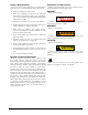
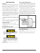
Wheel Guard Installation 1. Unscrew the nuts that lock the two bolts on the wheel guard support pin holes and take out the bolts. 2. Fit the wheel guard tube into the support pin, lining up the two sets of holes. 3. Fit the two bolts into the holes and attach the wheel guard on to the support by tightening up the nuts. Connect to Power Your factory trained COATS® Service Technician should do the final check to verify the power installation before connecting the balancer to a power supply.
Specifications Wheel Diameter Range 8 - 23 inches (203 - 584 mm) Wheel Width Range 1.5 - 20 inches (40 - 510 mm) Maximum Outside Tire Diameter Up to 35 inches (900 mm) Maximum Tire/Wheel Weight 100 pounds (45.4 Kg) Mounting Shaft Diameter 40 mm Standard Accessories • 8112107 Cone Spring • 8112098 Small Cone • 8112099 Medium Cone • 8112100 Large Cone • 8112106 Small Pressure Drum with Ring • 8113175 Wheel Weight Hammer • 8112103 Hub Nut • 8309011 Caliper Features Resolution (Round Off Mode) 0.
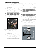
ÌBalancing Your First Tire 1. Turn the machine OFF then ON (resets machine). 7. Raise hood after tire stops rotating. Note: The machine wakes up using standard clip-on wheel weight locations (C1 & C2) and wheel dimensions. Note: Wait for wheel to stop before raising the hood. 2. Mount a tire/wheel on the balancer that will use standard clip-on wheel weights. 8. Rotate wheel to inboard (left plane) position of unbalance. 9. Attach inboard (left plane) corrective weight.
Principle Operating Parts Know Your Unit Compare this illustration with the unit before placing it into service. Maximum performance and safety will be obtained only when all persons using the unit are fully trained in its parts and operation. Each user should learn the function and location, of all controls. Note: Throughout this manual wheel weights are referred to as Clip-on or Tape-A-Weight®. Figure 5 shows an example of each weight.
Using The Offset Arm When not in use store the offset arm in the home position as shown in figure 7. Offset Arm In Home Position Rounding When the machine is switched on, its default setting is to show the unbalance to the nearest five grams (rounding up or down as necessary) or to the nearest 1/4 ounce if data output in ounces has been set.
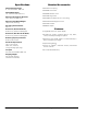
Mounting Wheel On Spindle Shaft Standard Back Cone Mounting Select the most appropriate mounting method for the wheel you are balancing. Using the proper method ensures secure mounting and safe balancer operation, and prevents damage to the wheel. Most original equipment and steel wheels can be mounted properly using this method. The wheel is centered on a cone from the inner side of the hub. On most wheels, the inner side of the wheel hub usually has the most uniform surface for wheel balancing.
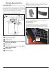
Standard Front Cone Mounting A wheel should be centered by the outer side of the hub only when the inner surface will not provide an accurate surface to center on. Figure 9 - Front Cone Mounting 1. Select the cone that best fits the center hole in the wheel. 2. Lift the wheel onto the shaft and slide it back against the shaft faceplate. 3. Slide the cone onto the shaft and into the center of the wheel. You will need to lift the tire to seat the cone in the center hole. 4.
Setting Wheel Dimensions (DIM) Before a wheel can be balanced, wheel dimensions must be entered into the computer. Definition of DIM W = Width The width of the wheel at the rim flanges, measured with the calipers as shown in figure 12. A2 = Offset The distance measured from the balancer (“0” on offset arm) to outer plane of the rim (outer weight location). Typically used in ALU programs. D2 = Diameter The diameter as measured at the A2 weight location. Typically used in ALU programs.
Wheel Data Entry (W, D, A) 1. Press . The machine is ready to receive the WIDTH (W) measurement (the corresponding LED will light). 2. Measure rim width using the caliper provided with the balancer (figure 12). 9. Read the machine/rim distance on the gauge. 10. Press or until the correct OFFSET number is set in the right display window. 11. Lower hood and press to spin wheel. Note: If you hold down or the numbers will spool up or down quickly making data input all the more rapid.
Balancing Programs Dynamic Balancing A variety of wheel configurations can be balanced using this wheel balancer. Read through this section, it will help you determine which program and options are best suited for certain wheel assemblies. To perform a balancing cycle: • Mount the wheel on the shaft using the most appropriate method. Refer to Mounting Wheel on Shaft, pages 8 & 9. • Remove any balancing weights, stones, dirt or other foreign bodies from the wheel.
Aluminium Wheel Choose from 5 ALU programs that represent typical corrective weight positions for aluminum wheels using a dynamic balance. The balancer’s ALU programs calculate out of balance values based on the wheel dimension measurements (DIM) entered for the tire/wheel assembly. ALU (Aluminum Wheels) - To balance aluminium wheels you usually use a self-adhesive weight location that is positioned differently from the clip-on weight position(s) used in standard balancing.
Attaching Corrective Weights Match Balance (Optimization) WARNING • Rotate the wheel until the center indicator light flashes and you hear a confirming beep. • Attach the corrective clip-on weight amount at topdead-center (12 o’clock) on the tire/wheel assembly. If the program ALU 1P is running, place the corrective Tape-A-Weight™ amount at the exact position and plane chosen when entering the wheel measurement data. • Lower hood and press to spin wheel and check balance.
OPT 1 • Mount the rim without the tire on the balancer. • Press • Turn it until the valve (or hole) is at 12 o’clock. • Make the forth spin. At the end of the spin, the OPT program is complete, and the machine displays the corrective weight amounts to balance the wheel. • Press . • Make the first spin (as instructed by the display). At the end of the spin, the program goes into its second stage. OPT 2 • Remove the rim from the balancer. .
Calibration Program Remember: Remove the 100 g (3.5 oz) sample weight at the end of the procedure. First Sensitivity Calibration This program needs to be run whenever the settings appear to be out of tolerance or when the machine requests self-calibration spontaneously by displaying the message “Er1 CAL”. • Select a wheel of average size and weight, preferably with a limited unbalance, and mount it on the shaft. • Enter the correct wheel dimensions for the wheel. • Press or gram LED lights up.
Diagnostic Procedures After Balance Vibration Problems If vibration is still present after balancing the wheels and driving the vehicle on smooth pavement, remove the wheels and recheck the balance. If a wheel is out of balance the cause may be: • Wheel was not mounted/centered correctly on the balancer. • A weight has come off the wheel (possibly the wrong clip style). Remove the other weights from the wheel and rebalance. • Foreign material inside the tire.
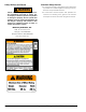
Troubleshooting Listed below are faults that the user can remedy if the cause is found to be among those indicated. Any other defect or malfunction will require the attention of a qualified technician: Contact your nearest BaseLine™ service center. ERROR CAUSE REMEDY Machine fails to switch on, with no light showing at the main switch. No power at the socket. ➤ Test the main voltage. ➤ Check the electrical power circuit installed in the workshop. Defective main plug.
Error Display The machine recognizes a number of incorrect operations and displays this as an error message. ERROR CODE DESCRIPTION Er1 CAL Error in first sensitivity calibration. Do the first sensitivity calibration procedure. Er2 CAL Error in first sensitivity calibration. Do the first sensitivity calibration procedure. Er3 CAL Calibration was done without using the 100 g standard weight. Repeat calibration with the correct calibration weight.
Maintenance Instructions The balancer requires only minor maintenance to keep the unit operating properly. 1. Keep the display clean and clear. Use a damp cloth. Do not use cleaners or solvents which leave oily or filmy residues behind. 2. Keep the adapters, cones, faceplate, threaded shaft, pressure cup, and hub nut clean. Grease and dirt buildup will cause inaccurate balancing and premature wear. Clean these items at least once a day with a vaporizing solvent. 3.
Glossary Of Terms Balancer Flange – Disk that mates with the disk of the wheel mounted to the balancer. The flange also serves to keep the wheel perfectly perpendicular to its axis of rotation. Balancing Cycle – Sequence of operations performed by the user and the machine, beginning from the start of the wheel spin to the time that the wheel is stopped; at a standstill, after the out of balance signals are acquired and the relative values calculated.
Notes 22 • Important: Always read and follow instructions.
Notes Important: Always read and follow instructions.
85607560 01 04/2011 © Copyright 2011 Hennessy Industries and COATS® All Rights Reserved.