
Installation Guide

9 After marking, remove header assembly [8]. Drill a 3/16” diameter hole thru the finished wall
material at the marked wall location. Drill a 1/8” diameter pilot hole approximately 2” deep into the
blocking behind the finish wall material.
DO NOT DRILL 3/16” HOLE INTO BLOCKING
10 Reassemble the header assembly to the fixed panel glass and the wall mount header
bracket. Check the header for level. Lightly tap the wall mount bracket to achieve level. Carefully
remove the header assembly and completely tighten the Flat Head Screw from Step 9. Final in-
stall the header assembly to the panel glass and wall mount bracket. Tighten the set screws in
the wall mount bracket.
NOTE: Set screws should be on the top of
the header bracket.
Do not over-tighten screws.
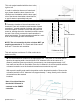
Next, screw the Header Bracket Insert onto the wall with the supplied #10 x 3” Flat Head screw.
Install the Header Bracket Insert with the adjustment slot in the vertical direction. This will allow for
a small amount of adjustment to make sure the header is level.
Do not completely tighten the NEW Flat Head Screw at this point.
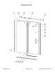
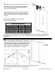
WALL MOUNT HEADER
BRACKET INSERT
SET SCREWS
WALL MOUNT HEADER
BRACKET
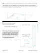
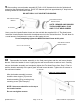
After the header assembly is secure,
install the door stopper [13] onto the
header assembly [8] by screwing in top
mounting screw. (See Example)
COMPLETED HEADER ASSEMBLY
SET SCREWS
MOUNTING SCREW
PANEL GLASS
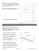
NOTE: REMOVE AND DISCARD
THE INCLUDED WALL PLUG
AND 2” FLAT HEAD SCREW
WALL MOUNT HEADER
BRACKET INSERT
#10 x 3” Flat Head Screw
QCI5279 Rev. 0 Page 10 of 15 Date Certified: 06/21/2016