
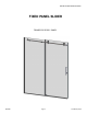
Installation Guide

QCI0280 Page8 Cerfied6/27/14
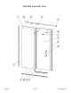
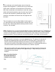
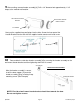
7Using suction cups, set the Glass Panel into the
U-channels on the appropriate side. Use different
sizes of setting blocks to make exposed edges of
the glass level and plumb.**
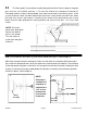
Refer to the sizing chart below to properly orient the
Glass Panel according to the unit range. Measure-
ment is from edge of glass to the header bar assem-
bly hole*
Exposed edges MUST be level and plumb
before moving to next step.
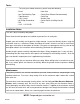
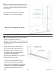
8Once the Stationary Glass Panel [1] has been in-
stalled, attach the roller bar header assembly [8] to the
top of the panel glass (see example). Once in place,
slightly loosen the screw inside to allow for adjust of the
header bar. Once adjusted to proper length and leveled,
tighten the screws.
With the header assembly [8] mounted, use a pencil to
mark the location where it sits flush against the door side
wall as shown.
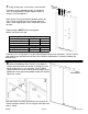
**Different sizes setting blocks may be required depending on level conditions. Various sizes of
setting blocks are provided and can be used in different combinations (stacked) to obtain the
desired result.
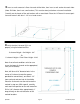
*Panel Glass Sizing Chart
Unit Range Wall Side Door Side
44 1/2" - 45 3/4" 5 1/2" 6 7/8"
45 3/4" - 47 1/2" 6 7/8" 5 1/2"
56 1/2" - 57 5/8" 5 1/2" 6 7/8"
57 5/8" - 59 1/2" 6 7/8" 5 1/2"
D
o
o
r
S
i
d
e
O
u
t
s
i
d
e
of
Show
e
r
W
a
l
l
S
i
d
e
MarkWallHere