
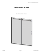
Installation Guide

QCI0280 Page10 Cerfied6/27/14
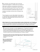
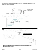
11The Door guide [11] can now be installed along the threshold. From the edge of the panel
glass that was just installed, measure 1 1/2” from the inside of the Horizontal U-channel [4].
Place door guide as shown in picture below, then mark the two holes to drill with a pencil. Insert
a small amount of silicon into each drilled hole, then insert a wall anchor into each hole. (Note:
Drill hole, then insert a wall anchor.) Carefully cut the heads off the wall anchors with a razor
blade. Place the door guide back in correct position and secure it with #8 x 1-1/2” truss head
screws.
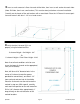
1.
Roller
Assembly
2.
Anti-Jump
Assembly
Header Bar
Roller
Assembly
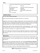
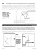
12Disassemble the two Rollers [7] and secure to door panel glass. (See example 1).
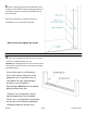
With rollers mounted onto the door panel, make sure the rollers are rotated to their lowest posi-
tion so that the door panel does not hit the ground or u-channel during installation. Then carefully
lift the door panel into place so the rollers rest on top of the roller bar assembly. Holding the door
in place, install the anti-jump assembly below the roller bar assembly in the two holes provided
to hold it in place. (See example 2).
NOTE:
Anti-jump is
cammed and
should be in-
stalled with a
1/16” or less
between the
itself and the
header bar.
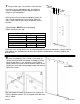
NOTE: The center
piece of the door guide
adjusts the width of
glass it can accept.
Turn the center to
match your door glass
thickness.
MounngScrews
CenterWidthAdjustment