
Operation Manual

EN
page 42
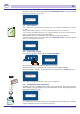
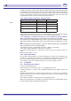
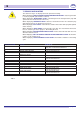
Nominal range of current per
phase (AMPERE)
Cable section
mm
2
0-10 1
10-16 1,5
16-25 2,5
25-32 4
32-50 6
MAX 0,5m
Table 2
Fig. 5
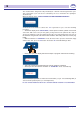
Fig. 6
6.3.2 Electrical connection
The electrical connection shall be carried out in accordance to the local laws in force.
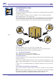
Moreover, the machine has a clamp at the back indicated by the symbol
that is used as
equipotent connection among different apparatuses, to prevent electrostatic currents.
Theelectricalsupplycablemustbenew,exible,andaccordingto"har"H07RN-Foralocal
validequivalent.Thecablesizeisdimensionedaccordingtothepower,aspertab2.
Ifthemachineisttedwithathree-phasepump,check the correct motor rotation (right
rotation as per arrow on the casing). This is not needed if the pump is a single-phase model
(standard).
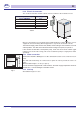
6.3.3 Water connection
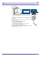
Connect the machine draining hose to the connection located at rear, under the back-
panel.
The drain tube shall always be connected to a siphon in order to prevent the release of
odors.
Maximum drain height = cm. 50 (see pict. 6).
Inthosemachinesequippedwith“watersoftener”thewatersupplytemperatureshallnot
exceed40C°,toavoiddamagestothelters’resins.
6.3.4 Start-up
At installation engineer’s care.