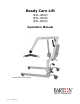
Ready Care Lift (RCL-4002) (RCL-4500) (RCL-6002) Operation Manual (Model RCL-4002 Shown) Rev A March 2007
TABLE OF CONTENTS Warnings Warranty Ready Care Lift (Model 4002) Specifications Ready Car Lift (Model 4500) Specifications Bariatric Ready Care Lift (Model 6002) Specifications Ready Care Lift Overview Assembly Operation Ready Car Lift Overview Operation (special instructions for lifting from a vehicle Slings - Loading in a Seated Position - Loading in a Recumbent Position - Positioning the Legs - Sling Care Transfers Interchangeable Battery System Overview IBS Technical Data Placing and Removing the Batte
WARNINGS DO NOT ATTEMPT TO SETUP OR OPERATE THE READY CARE LIFT WITHOUT THOROUGHLY REVIEWING THE CONTENTS OF THIS MANUAL! FAILURE TO DO SO MAY RESULT IN SERIOUS INJURY, EQUIPMENT FAILURE, AND/OR VOID WARRANTY. If you have any questions regarding the setup or operation of the Ready Care Lift, please contact: AFFIX DEALER CONTACT INFORMATION HERE Or contact Barton Medical: 1-800-387-7103 THE READY CARE LIFT FROM BARTON MEDICAL HAS BEEN INSPECTED TO C.S.A. (CANADIAN STANDARDS ASSOCIATION) GUIDELINES.
WARRANTY Warranties are limited to manufacturer’s defects and exclude the effects of normal wear and tear, unintended use, operator abuse, concussive impacts and external factors including exposure to heat lamps, vapours, chlorine and other corrosive substances. Barton Medicals’ liability under warranties is limited to replacing defective parts and does not extend to consequential damages. Warranties are voided by unauthorized repairs or modifications to the equipment.
READY CARE LIFT SPECIFICATIONS PRODUCT NUMBER: RCL-4002 OPERATION: Electric Actuator POWER SOURCE: 24 V (4.
READY CAR LIFT SPECIFICATIONS PRODUCT NUMBER: RCL-4500 OPERATION: Electric Actuator POWER SOURCE: 24 V (4.5 Amp) BOOM, Highest Position: 65-¾” (167 cm) BOOM, Lowest Position: 29” (73.
BARIATRIC READY CARE LIFT SPECIFICATIONS PRODUCT NUMBER: OPERATION: POWER SOURCE: BOOM, Highest Position: BOOM, Lowest Position: MAXIMUM CAPACITY: OVERALL LENGTH: BASE WIDTH, Closed: RCL-6002 Electric Actuator 2 X 12-Volt sealed, lead acid 71” (180 cm) 23.75” (60 cm) 700 lbs. (272 kg.) 53.5” (136 cm) inside: 21” (53.5 cm) outside: 25” (63.5 cm) inside: 49” (124.5 cm) outside: 53.25” (135 cm) 3” (7.6 cm) 4” (10.2 cm) 136 lbs. (61.8 kg.
READY CARE LIFT OVERVIEW Lift Arm Steering Handles Lift Arm End Cap Interchangeable Battery System Actuator Sling Hanger Mast A (see detailed view) Rear Locking Casters VIEW A Detailed View of Foot Pedal Assembly Foot Pedal Textured Sure Grip Tie Rod End Tie Rod 6
ASSEMBLY 1. Without using a knife, open the carton and remove the packaging which secures the lift in the box. When removing the mast be careful as the lifting arm and actuator are fastened to the mast. 2. Once all the parts have been removed from the carton, ensure you have all the components which make up the lift. If there is a discrepancy please call your supplier or Noram Solutions at 1-800-387-7103 3. Place the base on the floor and lock the rear castors to prevent movement while assembling.
OPERATION CHARGE YOUR READY CARE LIFT EVERY NIGHT USING THE CHARGER PROVIDED. 1. The lift should not be operated (more than two lifts) when the battery level indicator begins to flash yellow. Be sure to charge as soon as possible. Extended use of the battery pack when the low battery indicator is flashing may permanently affect the capacity of the batteries in the pack. 2. The battery pack should be charged while on the lift.
READY CAR LIFT OVERVIEW Lift Arm Lift Arm End Cap Steering Handles Actuator Mast Rear Locking Casters 9 Sling Hanger
SPECIAL INSTRUCTIONS FOR LIFTING FROM A VEHICLE 1. For a vehicle extraction, the safe use of the lift requires two caregivers. 2. With doors on both sides of the vehicle open, one caregiver can access the patient from inside the vehicle while the other works from the outside. 3. Assess the size and shape of the patient; particularly their circumference. Visually compare them to the sling and choose the smallest sling possible. 4. Lean the patient forward.
LOADING IN A SEATED POSITION If the user is seated in a wheelchair, make sure the wheelchair is in a locked position before proceeding. If the user is in bed, either bring the head of the bed to the upright position or follow the procedure for loading in a recumbent position. 1 2 1. Stand behind or to the side of the user and hold the sling with the smooth side facing the user's back. 3 2. Work the sling down the back, leaving the top of the commode aperture at the base of the spine.
LOADING IN A RECUMBENT POSITION If the user is in bed, make sure the surface is flat and adjusted to a comfortable working height. 1 2 1. Turn the user to face you and hold the sling sideways with the smooth side facing the user. Gather the sling halfway and place behind the user's back with the smooth side up. 2. Turn the user on his/her back and pull the gathered material towards you. The sling should now be flat and centered underneath the user. 3 4 3.
POSITIONING THE LEGS Three leg positions are possible with the General Purpose Sling: open, divided and closed. The closed position is for transfers, the open and divided positions are for toileting and bathing as well as transfers. The closed position is often felt to be more dignified, controls muscle spasms and is beneficial for transfers of amputees. To achieve the open position, bring the leg bands up between the thighs and attach the leg straps to the ends of the carry bar.
SLING CARE The body of the general purpose sling is made of quick-dry, heat set and flame retardant polyester. The straps are high-strength nylon webbing. The padding is closed-cell polyethylene foam. There is no latex in Noram slings. While the materials comply with applicable standards for strength, shrinkage and flammability, slings are subject to wear and tear, which increases with usage. Before each use check for fraying or cuts/tears in the straps and body of the sling.
TRANSFERS CHAIR TO BED TRANSFER 1. Choose the appropriate sling for your resident and place it under them. (For more information on using slings please see the Slings section of this manual). 2. Adjust the legs of the Ready Care Lift to straddle the chair. Use your left foot to push the left pedal of the leg adjustment to widen the legs to the correct width. The leg assembly has three width positions. 3.
TRANSFERS BED TO CHAIR TRANSFER 1. Choose the appropriate sling for your resident. 2. Turn the resident on their side and position the sling at their back. Spread one side of the sling out and turn the resident onto it and over further onto their side. Spread the other half of the sling out and turn the resident onto their back. 3. Position the legs of the sling under the residents legs. 4.
INTERCHANGEABLE BATTERY SYSTEM OVERVIEW Battery/Charge Level Indicator Emergency Stop Plug In Ports (see below for detail view) Bottom View Of Electronics Pack Hand Control (400-125) Overview Hanger Emergency Lowering Hand Control Plug (into Electronics Pack) Charger Port Up Actuator Port Down Secondary Actuator Port Hand Control Port 17
INTERCHANGEABLE BATTERY SYSTEM 1. It is highly recommended that the batteries be fully charged on a daily basis. This action will greatly extend the life to the battery. 2. The Battery Pack may be charged while on the lift by inserting the charger plug into the charger port on the bottom of the Electronics Pack (see Electronics Pack Bottom View on page 14). This is the recommended method of charging. 3. The Battery Pack may also be charged using a separate wall-mounted charging station (optional).
IBS TECHNICAL DATA IBS-130 Complete System (Includes Battery, Electronics Pack, Hand Control and Charger) Individual Components of IBS-130 Charger Battery Pack Electronics Pack Hand Control (400-141) (400-155) (400-143) (400-125) Control Unit Voltage (actuator): Operating element: AC Adaptor: Weight: 24V - DC (max 6.3A) Hand control 28V 500mA 0.9 Kg (2 lbs) Battery Voltage: Capacity: Weight: 24V - DC 4.5 Ah 4 kg (8.
PLACING AND REMOVING THE BATTERY PACK Placing the Battery Pack on the Lift To place the battery on the electronics pack, hold the battery pack by the top handle and place your other hand on the side of the pack. Position the metal tabs on the back of the battery pack into the metal slots on the electronics pack mounting bracket. Once in position, push the battery pack down, so the plug on the electronics pack sits in the battery pack.
INSTALLING THE CHARGING STATION (400-157) 2 13/16” (72 mm) 4 3/8” (111 mm) 13/16” (21 mm) 1 1/4” (32 mm) 6 3/8” (162 mm) The above schematic shows the location of all of the mounting holes. The wall mounted charging station should be fastened to the wall using 1/4” screws with the appropriate wall anchors (will vary depending on your facility’s wall structure).
READY CARE LIFT SCALE (OPTIONAL) Scale Hanger Cover Hanger Weight Display Lbs/Kg Indicator Switch Between Kgs and Lbs.
SCALE ATTACHMENT (OPTIONAL) Parts required to install: 1 - 3/8" N.C. x 2" hex head bolt 1 - 3/8" N.C. nylock nut 2 - 3/8" x 1/2" buttite spacer 1. Slide lift arm end cover up onto the lift arm and remove the nut and bolt which secures the hanger and remove the hanger. 2. Insert one buttite spacer onto the 3/8" N.C. hex head bolt. 3. Using the 3/8" N.C. hex head bolt, guide the 1/2" buttite spacer inside the lift arm assembly. 4. Place the safety lock cover (#5) onto the hanger scale assembly hook.
SCALE OPERATION (OPTIONAL) Once installed, the scale becomes a permanent part of the Ready Care Lift. To weigh a patient: 1. Hang the appropriate sling on the hanger ensuring that the sling does not touch the floor. 2. Push the ON button to power the scale. There will be a display of 0-0-0-0 across the window. The scale should automatically stop on zero (0.0). If not, push the ZERO button to achieve zero weight. 3. Proceed to lift the patient and the weight will be displayed.
READY CARE LIFT - MAJOR COMPONENTS (Lift Arm 101-074) (Bariatric Arm 101-074B) (Ready Car Lift Arm 102-671) Mast 101-901 Hanger Assembly (see detail view) (Bariatric 101-081B) (Car Lift 102-669) Boom End Cover (100-039) 350 mm Actuator (400-131) Foot Pedal (101-065) (Bariatric 101-065B) Tie Rod Assembly (see detail view) Main Frame (101-080) (Bariatric 101-080B) 1/2” x 3 1/2” Shoulder Bolt For Leg (100-021) 4” Locking Caster (100-010) Leg (101-072) (Bariatric 101-072B) 25 3” Swivel Caster (100-0
HANGER ASSEMBLY - DETAIL VIEW Hanger Cover (101-045) Retaining Clip (100-049) Hanger (101-173) 1.015 id x 1.
INTERCHANGEABLE BATTERY SYSTEM - BARIATRIC Battery Pack Handle Battery Pack Emergency Stop Button Electronics Pack Emergency Lowering (depress with small object) Battery Level/ Charge Indicator HAND CONTROL OVERVIEW ELECTRONICS PACK BOTTOM VIEW Charger Port Port for Hand Control Plug-In Port for Actuator Plug-In 27 Up Down
PLACING AND REMOVING THE BATTERY PACK - BARIATRIC Placing the Battery Pack on the Lift To place the battery on the electronics pack, hold the battery pack by the top handle and place your other hand on the back of the pack. Place the battery on top of the electronics pack and push the battery toward the mounting plate until the metal tab on the top of the battery pack locks into place.
MAINTENANCE The following is a checklist of the areas of the READY CARE LIFT that should be inspected on a regular basis. It is recommended to inspect the lift monthly or bi-monthly. This will depend on frequency of use. Any part which appears worn or wearing should be replaced immediately for safety of caregiver and patient.
TROUBLESHOOTING 1. Ready Care Lift will not operate in either direction: -ensure the actuator (motor) is plugged in and secure -emergency switch is turned off (turn button clockwise) -check battery level indicator -ensure the hand control is connected to the electronics pack -check for cuts in the hand control wire 2. Ready Care Lift operates in "UP" position only: -small switch at the base of the actuator is engaged. To disengage, lift up on actuator and lift arm.
Barton Medical Warranty Card Name: Address: Phone: Fax: Product: Serial #: Date of Purchase: Date of Installation: Was your product installed by Barton Medical or a Barton appointed agent? If no, please specify (name/address): Was your product received in good condition? Signature: (please print name): By returning this card, I acknowledge receiving the aforementioned product in good working order and physical appearance.