
Programming Manual

i480e&i480e-MD2 Programming Manual
33 / 139
an output.
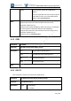
(PIO 18) maps to UART_DATA_OUT. This can be configured as an
input or an output.
(PIO 19) maps to PCM_CLK_OUT. Set this to output to the PCM_CLK
pin. This line is output only.
(PIO 20) maps to AIO0.
(PIO 21) maps to AIO1.
PIO lines above 21 map to nothing and cannot be mapped or
written.
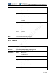
For I480e the PIO lines map to other pins as follows:
(PIO 0-12) have no mapping. They are always PIO 0-12.They can be
configured as inputs or outputs.
The smaller packages such as Chip Scale Package (CSP) does not
have PIO8..12.
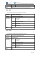
(PIO 13..15) may be mapped if required. The exact signal routing is
dependent
on which package is being used. On smaller packages, such as CSP,
you must map PIO13-15 if you want PIO instead of UART UART_RX,
UART_TX and UART_CTS.
On the BGA package PIO13..15 have their own pins, but if mapped,
will be connected to the UART_RX, UART_TX and UART_CTS pins as
well. Whether mapped or not, these PIO pins may be configured as
inputs or outputs. For each pin, if mapped and set as output, both
(UART and PIO) pins are driven. If mapped and set as input, the
UART pin is connected and the PIO pin is n/c.
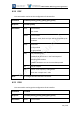
(PIO 16) maps to the UART_RTS pin. This can be configured as an
input or an
output.
(PIO 17) maps to the PCM_IN pin. This can be configured as an input
or an
output.
(PIO 18) maps to the PCM_OUT pin. This can be configured as an
input or an output.
Barrot Confidential