
Specifications


58 Barracuda Load Balancer Administrator’s Guide
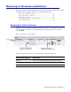
Front Panel of the Barracuda Load Balancer
Figure B.1 and Figure B.2 illustrate the front panels for each model.
Barracuda Load Balancer 240, 340, and 440
Figure B.1 shows the front components as described in Table B.1.
Table B.1 describes the front components on the Barracuda Load Balancer 240, 340, and 440.
Figure B.1: Barracuda Load Balancer Front Panel for models 240, 340, and 440
Table B.1: Front Panel Descriptions for Barracuda Load Balancer 240, 340, and 440
Diagram Location Component Name Description
1 WAN port Port for WAN connection
2 LAN port Port for LAN connection
3 Reserved for future use
4 Reserved for future use
5 Traffic Blinks when the Barracuda Load
Balancer is processing traffic
6 Data I/O Blinks during data transfer
7 System Power Displays system power
8 Reset Button Resets the Barracuda Load
Balancer
9 Power Button Powers on/off the Barracuda
Load Balancer
1
2
3
4
5
6
7
8
9