
Instruction Manual
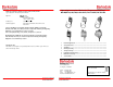
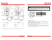

Contacts: color code and function
Lower contacts Upper contacts
C = Common = purple C = brown
NC = Normally Closed Contact = blue NC = orange
NO = Normally Open Contact = red NO = yellow
Fig. 11: Temperature switch type L2H-…
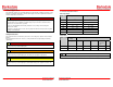
Contact Protection
The micro switches used are normally suitable for both direct and alternating current operation.
Inductive, capacitive and lamp loads may, however, considerably reduce the life expectancy of a micro
switch and, under extreme circumstances, even damage the contacts.
Depending on the application spark suppression and current limiting is recommended (see succeeding
figures).
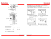
Fig. 1: Protection in case of capacitive loads
R1: Protection against starting current
rushes R2,R3: Protection against high
discharge currents
Fig. 2: Lamp load provided with resistance in
series or parallel connection to switch
of condensers
Fig. 3: Protection in case of continuous
current and inductive load by recovery
diode
Fig. 4: Protection in case of alternating
current and inductive load by RC-link
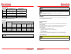
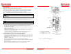
¾“ NPT
Option adjustable
hysteresis (RD)
Adjustment knob
High circuit S2
Adjustment knob
Low circuit S1
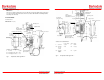
22 (0.87)
51 (2.01)
102 (4.016)
Ground screw
115 (4.53)
86 (3.39)
71 (2.795)
51 (2.01)
½" NPT
19 (0.756)
ø14.5 (0.43)
63.5 (2.5)
MS
R1
R2
R3
Load
C cable
MS
R
R
MS
MS
U
=
Diode
Load
MS
U
c
Load
R
5
12