INSTALLATION INSTRUCTIONS CHDM DEHUMIDIFICATION MODULE for use with CH3S1 CH4S1 CH5S1 Bard Manufacturing Company, Inc. Bryan, Ohio 43506 Since 1914...Moving ahead just as planned.
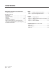
CONTENTS Getting Other Information and Publications For More Information ............................................... 3 Wall Mount General Description ............................................................ 4 Shipping Damage ................................................. 4 General .............................................................. 4 Installation ....................................................... 4 & 5 Sequence of Operation .........................................
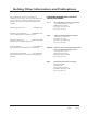
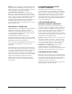
Getting Other Information and Publications These publications can help you install the air conditioner or heat pump. You can usually find these at your local library or purchase them directly from the publisher. Be sure to consult current edition of each standard. FOR MORE INFORMATION, CONTACT THESE PUBLISHERS: ACCA Air Conditioning Contractors of America 1712 New Hampshire Ave. N.W.
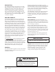
DESCRIPTION The CHDM dehumidifier is designed to be used with Bard 3 through 5 ton CH heat pump models. It will be installed in the outdoor section of the CH unit. The dehumidifier incorporates a complete refrigeration system. It will share the high & low voltage control from the CH control panel. The CHDM is for use in CH*S Series units with or without CHERV or CHCRV. The CHDM cannot be used in units equipped with economizers CHEIFM.
DRAIN: Connect a drain trap to the drain fitting under the bottom of the dehumidifier section of the unit. The drain connection is a ¾" female pipe fitting. The use of a trap is required to ensure proper drainage. AIR CHANNEL ASSEMBLY: (See Figure 3.) Remove cover plate in unit and cut out the insulation. On CH3S1 models, the duct extension is to be removed and a new piece of foam (supplied) added to the bottom of the air channel assembly.
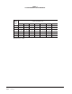
TABLE 1 CH DEHUMIDIFIER PERFORMANCE Dry Bulb Temp F Water Removal lb./hr (PPD) Relative Humidity % Rh 50 55 60 65 70 75 80 65 1.0 (24.0) 1.3 (31.2) 1.5 (36.0) 1.7 (40.8) 2.0 (48.0) 2.2 (52.8) 2.4 (57.6) 70 1.2 (28.8) 1.5 (36.0) 1.8 (43.2) 2.0 (48.0) 2.3 (55.2) 2.6 (62.4) 2.8 (67.2) 75 1.4 (33.6) 1.7 (40.8) 2.0 (48.0) 2.4 (57.6) 2.7 (64.8) 3.0 (72.0) 3.3 (79.2) 80 1.7 (40.8) 2.0 (46.0) 2.4 (57.6) 2.7 (64.8) 2.8 (67.2) 3.4 (81.6) 3.7 (88.8) 85 2.0 (48.0) 2.3 (55.2) 2.8 (67.2) 3.
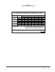
TABLE 2 CHARGING PRESSURE LABEL SYSTEM REFRIGERANT PRESSURE CHART Return Air Temperature 70° DB 75° DB 80° DB 85° DB Pressure Low Side High Side Low Side High Side Low Side High Side Low Side High Side Low Side pressure: ±2° High Side Pressure:±5° Relative Humidity % 50% RH 55% RH 60% RH 65% RH 70% RH 75% RH 80% RH 96 97 98 100 102 104 106 248 253 258 261 265 269 273 110 112 114 116 117 118 120 270 276 282 288 294 298 303 115 119 123 127 132 136 140 297 306 315 324 333 342 351 120 127 134 141 148 153 15
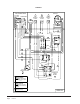
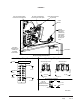
FIGURE 1 Overload Unit Control Panel 230/208-60-1 C 13 18 Freeze Thermostat C 12 Compressor 7 Ground Black Brown Black/White Purple/White S R 29 Purple 11 Relay #2 3 2 Contactor 28 4 5 Blk/White Blue Blue Yellow L1 L2 10 9 Red Orange Y1 High Pressure Control 1 3 Black Yellow R Low Pressure Control Black Green DH 16 Fan Motor Red G 19 15 Red TAPE OFF 14 Red Low Voltage Term.
FIGURE 2 Run wires to terminal block for 460 Volt unit control panel Run wires to terminal block for 230 Volt unit control panel Route green ground wire to ground lug Control Panel Remove knockout and insert strain relief bushing from opposite side of panel. Run wires into bushing and close.
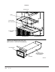
FIGURE 3 5(029( 3/$7( 6&5(: 326,7,21 $1*/( 72 /()7 $6 6+2:1 6(/) 7$33,1* 6&5(:6 $,5 &+$11(/ $66 < '(+80,',),(5 $66 < 5(029( (;7(16,21 )25 &+ 6 81,7 6(( 3$*( 2) ,16758&7,21 0$18$/ '8&7 (;7(16,21 $,5 &+$11(/ $66 < 0$,1 3$57 72 %( 86(' 21 $// 02'(/6 6&5(:6 0,6 Manual 2100-506D Page 10 of 14
FIGURE 4 Filter Access Door Unit Right Side Control Panel Door Vent Option Door Dehumidifier Dehumidifier Access Panel Service Ports Hex grille pattern (under fill plate) Ø1.
CABINET and FUNCTIONAL COMPONENTS 6(;3 Manual 2100-506D Page 12 of 14
Draw ing No. Part No.
CABINET and FUNCTIONAL COMPONENTS Manual 2100-506D Page 14 of 14 Draw ing No. Part No.