NIO 2MP LED Display User Guide MDNC-2221 K5903058/04 09/10/2014
Barco nv President Kennedypark 35, 8500 Kortrijk, Belgium Phone: +32 56.23.32.11 Fax: +32 56.26.22.62 Support: www.barco.com/esupport Visit us at the web: www.barco.
Table of contents TABLE OF CONTENTS 1. Welcome! .......................................................................................... 3 1.1 1.2 About the product .. .. .. .. .. .. .. .. .. .. .. .. .. .. .. .. .. .. .. .. .. .. .. .. .. .. .. .. .. .. .. .. .. .. .. .. .. .. .. .. .. .. .. .. .. .. . 3 What’s in the box. .. .. .. .. .. .. .. .. .. .. .. .. .. .. .. .. .. .. .. .. .. .. .. .. .. .. .. .. .. .. .. .. .. .. .. .. .. .. .. .. .. .. .. .. .. .. . 3 2. Parts, controls and connectors .....
Table of contents 2 K5903058 NIO 2MP LED DISPLAY 09/10/2014
1. Welcome! 1. WELCOME! 1.1 About the product Overview Thank you for choosing this NIO 2MP LED Display! NIO 2MP LED Display is an industry-standard 2MP color display system with LED backlights for dependable diagnostic viewing in high-bright color. NIO 2MP LED Display provides an effective display solution for a multitude of applications and modalities.
1. Welcome! Keep your original packaging. It is designed for this display and is the ideal protection during transport and storage.
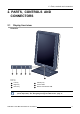
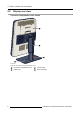
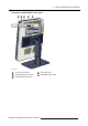
2. Parts, controls and connectors 2. PARTS, CONTROLS AND CONNECTORS 2.1 Display front view Overview 1 2 3 4 5 6 Image 2-1 Front view 4 2 Left key Right key 5 Standby key Power LEDs 3 Menu key 6 Bottom downstream USB 1 The key icons are displayed above the keys, adapted to the function that it is used for (menu dependent). See "Navigating through the OSD menus", page 17.
2. Parts, controls and connectors 2.
2.
2.
3. Display installation 3. DISPLAY INSTALLATION Prior to installing your NIO 2MP LED Display and connecting all necessary cables, make sure to have a suitable display controller physically installed in your computer. If you are using a Barco display controller, please consult the user guide delivered with it to do this. 3.1 Unlocking the height mechanism To remove the clip: 1. Position the display with its rear side facing you. 2. Pull the red clip out of the fixation hole in the foot. 3.
3. Display installation If, after installing the display of the system, you change the panel orientation while an image is on the screen, the result depends on the graphic board and the resolution of the image. In some cases the image will be rotated automatically, in other cases it will not be rotated (e.g., when pixels would be lost after rotation). If necessary, change the image resolution in the display control panel and restart the system after changing the orientation. 3.
3. Display installation 1. Connect the DVI or DP of the display controller to the DVI or DP connector of the display. 2. If you want to make use of the display’s USB upstream connector, connect a PC USB downstream connector to the display’s USB upstream connector. 3. If you have chosen to use the display’s USB downstream connector, connect a USB device to the downstream connector. 4. Connect the supplied external DC power supply to the +24 Vdc power input of the display. 5.
3. Display installation 3.5 Routing the cables & Reattach the connector compartment cover To route the cables 1. Route all connected cables through the cable routing channel in the stand of your display. Tip: The cable straps at the inside of the connector compartment allow you to fix the cables for better shielding of the cables. To Reattach the connector compartment cover 1. Reattach the connector compartment cover by sliding the cover’s bottom in position and then push the cover’s top.
3. Display installation WARNING: Use an arm that is approved by VESA (according to the VESA 100 mm standard). Use an arm that can support the weight of the display. Refer to the technical specifications of this display for the applicable weight. Overview The panel, standard attached to the tilt & swivel foot, is compatible with the VESA 100 mm standard. So it can be used with an arm stand according to the VESA 100 mm standard. Therefore, the tilt & swivel foot must be removed from the panel. 1.
3. Display installation 5. Remove the four screws fixing the foot while supporting the foot. 6. Attach the arm stand firmly to the panel using 4 screws M4 x 8 mm. 3.7 First time starting up Overview You are now ready to start up your NIO 2MP LED Display for the first time. 1. Switch on your NIO 2MP LED Display as described in "Standby switching", page 16. 2. Turn on the computer connected to your display.
4. Daily operation 4. DAILY OPERATION 4.1 Recommendations for daily operation Optimize the lifetime of your display Enabling the Display Power Management System (DPMS) of your display will optimize its diagnostic lifetime by automatically switching off the backlight when the display is not used for a specified period of time. By default, DPMS is enabled on your display, but it also needs to be activated on your workstation. To do this, go to “Power Options Properties” in the “Control Panel”.
4. Daily operation Maximize quality assurance The ’MediCal QAWeb’ system offers online service for high-grade Quality Assurance, providing maximum diagnostic confidence and uptime. Barco recommends to install MediCal QAWeb Agent and apply the default QAWeb policy at least. This policy includes calibration on regular intervals. Connecting to MediCal QAWeb Server offers even more possibilities. Learn more and sign up for the free MediCal QAWeb Essential level at www.barco.com/healthcare/qa. 4.
4. Daily operation 4.4 Bringing up the OSD menus How to bring up the OSD menus The OSD menu allows you to configure different settings to make your NIO 2MP LED Display fit your needs within your working environment. Also, you can retrieve general information about your display and its current configuration settings through the OSD menu. Bringing up the OSD menus can be done by: 1. If not already done so, switch on the display as previously described. 2. Illuminate the keys as previously described. 3.
4.
5. Advanced operation 5. ADVANCED OPERATION 5.1 OSD menu language About the OSD menu language By default, the OSD menu comes up in English. However, there’s a wide range of other languages available for the OSD menu of your NIO 2MP LED Display. To change the language of the OSD menu: 1. Bring up the OSD main menu. 2. Navigate to the Configuration > User Interface > Menu menu. 3. Enter the Language submenu. 4. Select one of the available languages and confirm. 5.
5. Advanced operation 5.4 Key indicator lights About the key indicator lights By default, after lighting up, the key indicator lights will dim again if no further actions are taken within the following 5 seconds. However, this behavior can be changed so that the key indicator lights are always on or always off. To configure the key indicator lights 1. Bring up the OSD main menu. 2. Navigate to the Configuration > User Interface > Indicator Lights menu. 3. Enter the Keys submenu. 4.
5. Advanced operation 4. Select Enabled/Disabled as desired and confirm. 5.7 Hibernate About hibernate Enabling hibernation will not only switch off the backlight but will also force the display to disable other functionalities so that power consumption is further reduced to a minimum. This happens after a specific period of time which can be manually adjusted. Hibernate can only be enabled on your display when the DPMS mode is enabled first. Therefore, please refer to "DPMS mode", page 20 to do this.
5. Advanced operation 5.9 Viewing modes About viewing modes The NIO 2MP LED Display can be used in two viewing modes: Diagnostic This mode provides the full calibrated luminance and is intended for using the display for diagnostic purposes. In this mode, the luminance is reduced to approximately half of the luminance. This is intended for using the display with office applications such as word processing.
5. Advanced operation DICOM User Gamma 1.8 Gamma 2.2 DICOM (Digital Imaging and Communications in Medicine) is an international standard that was developed to improve the quality and communication of digital images in radiology. In short, the DICOM display function results in more visible grayscales in the images. Barco recommends selecting the DICOM display function for most medical viewing applications.
5. Advanced operation To select a reading room: 1. Bring up the OSD main menu. 2. Navigate to the Configuration > Calibration > Reading Room menu. 3. Enter the Reading Room submenu. 4. Select one of the available reading rooms and confirm. 5.12 Display orientation About Display orientation Your display automatically detects its physical orientation (portrait or landscape) and, by default, automatically adjusts the image orientation to this.
5. Advanced operation Refresh Rate Preferred Orientation Color Depth Allows to manually select the refresh rate of the image source video input signal depending on the maximum refresh rate of the display controller connected to your display. Allows to change the orientation of the image source video input signal to landscape, portrait or to let the display automatically assign the correct orientation. Allows to change the color depth to 8 or to 10 bit. To manually set EDID timings: 1.
5.
6. Maintenance 6. MAINTENANCE General maintenance information The NIO 2MP LED Display does not require any scheduled maintenance or calibration activities. We recommend to use QAWeb with the Barco default tests and frequencies to calibrate and maintain the display or return the display to a Barco approved maintenance organization. In any case of doubts, contact the Barco Healthcare Division 6.
6.
7. Important information 7. IMPORTANT INFORMATION 7.1 Safety information General recommendations Read the safety and operating instructions before operating the device. Retain safety and operating instructions for future reference. Adhere to all warnings on the device and in the operating instructions manual. Follow all instructions for operation and use. Electrical Shock or Fire Hazard To prevent electric shock or fire hazard, do not remove cover. No serviceable parts inside.
7. Important information To fully disengage the power to the device, please disconnect the power cord from the AC inlet. Power cords: • • • • Use a power cord that matches the voltage of the power outlet, which has been approved and complies with the safety standard of your particular country. Do not overload wall outlets and extension cords as this may result in fire or electric shock. Mains lead protection (U.S.
7. Important information 7.2 Environmental information Disposal Information Waste Electrical and Electronic Equipment This symbol on the product indicates that, under the European Directive 2012/19/EU governing waste from electrical and electronic equipment, this product must not be disposed of with other municipal waste. Please dispose of your waste equipment by handing it over to a designated collection point for the recycling of waste electrical and electronic equipment.
7. Important information 零件项目(名称) 有毒有害物质或元素 Component name Hazardous substances and elements 汞 六价铬 铅 镉 Pb Hg Cd Cr6+ 塑胶外壳 o o o o 多溴联苯 多溴二苯 醚 PBB PBDE o o Plastic enclosure 散热片(器) o o o o o o Heatsinks 电源供应器 x o o o o o Power Supply Unit 风扇 o o o o o o Fan 文件说明书 o o o o o o Paper Manuals 光盘说明书 o o o o o o CD manual O: 表示该有毒有害物质在该部件所有均质材料中的含量均在 SJ/T 11363-2006 标准规定的限量要求以下.
7. Important information China Energy Label 按照中国 <<能源效率标识管理办法>> 本显示器符合以下要求 In accordance with The Regulation of the Implementation on China Energy Label 能源效率 This monitor is compliant with the following requirements > 0.85 Energy Efficiency (cd/W) 关闭状态能耗 < 1.0 Energy Consumption in off mode (W) 能源效率等级 2 Energy Efficiency Level 执行的能源效率国家标准编号 GB 21520-2008 Code of National Standard applied 7.
7. Important information 7.4 EMC notice General information No specific requirement on the use of external cables or other accessories except power supply. With the installation of the device, use only the delivered power supply or a spare part provided by the legal manufacturer. Using another can result in a decrease of the immunity level of the device. Electromagnetic emissions The NIO 2MP LED Display is intended for use in the electromagnetic environment specified below.
7.
7. Important information Immunity test IEC 60601 Compliance level Test levels Electromagnetic environment – guidance manufacturer and d is the recommended separation distance in meters (m). Field strengths from fixed RF transmitters, as determined by an electromagnetic site survey,3 should be less than the compliance level in each frequency range.4 Interference may occur in the vicinity of equipment marked with symbol: At 80 MHz and 800 MHz, the higher frequency range applies.
7. Important information Rated maximum output Separation distance according to frequency of transmitter power of transmitter 5 150kHz to 80MHz 80MHz to 800MHz 800MHz to 2.5GHz W d=1.2√P d=1.2√P d=2.3√P 10 3.8 3.8 7.3 100 12 12 23 At 80 MHz and 800 MHz, the separation distance for the higher frequency range applies. These guidelines may not apply in all situations. Electromagnetic propagation is affected by absorption and reflection form structures, object and people. 7.
7. Important information Indicates the device is approved according to the BSMI regulations Indicates the USB connectors on the device Indicates the DisplayPort connectors on the device Indicates the manufacturing date Indicates the temperature limitations6 for the device to safely operate within specs Indicates the device serial no.
7. Important information Indicates a medical device that can be broken or damaged if not handled carefully when being stored. Indicates a medical device that needs to be protected from moisture when being stored. Indicates the storage direction of the box. The box must be transported, handled and stored in such a way that the arrows always point upwards. Indicates the maximum number of boxes to be stacked on each other. 15 n Indicates that the box should be carried with two persons.
7. Important information Patent information This product is covered under the following intellectual property rights: US Patent RE43,707 7.7 Technical specifications Overview Product acronym MDNC-2221 Screen technology IPS-Pro Active screen size (diagonal) 540 mm (21.3”) Active screen size (H x V) 324,9 mm x 433,2 mm (12.79” x 17.1”) 4:3 Aspect ratio (H:V) Resolution Pixel pitch 2MP (1600 x 1200) 0.
7. Important information Dimensions with stand (W x H Portrait: (w x hmax x d) 378 x 625 x 235 mm (w x hmin x d) 378 x 525 x x D) 235 mm Landscape: (w x hmax x d) 491 x 565.5 x 235 mm (w x hmin x d) 491 x 465.5 x 235 mm Dimensions w/o stand (W x H 378 x 491 x 83.2 mm x D) Dimensions packaged (W x H 655 x 388 x 495 mm x D) Net weight with stand 12.6 kg (with glass) – 11.32 kg (without glass) Net weight w/o stand 7.6 kg (with glass) – 6.32 kg (without glass) Net weight packaged with 16.
7. Important information 7.8 Compatible display controllers Overview Barco strongly recommends to use a Barco display controller with your display. All Barco display controllers compatible with your display can be found in the options-tab on the product-page of your display on www.barco.com. A user guide of the display controllers is available on the cd-rom delivered with the unit. 7.