
user manual

50 FSN Series • User’s Guide • Rev 01
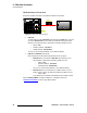
2. FSN-1400 Orientation
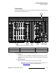
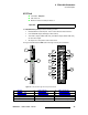
Card Descriptions
Following are descriptions of all M/E card components:
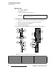
1) Ejectors
Use the card’s top and bottom Ejectors to remove (and re-insert) the card.
2) Card Power LED
The Card Power LED indicates power status for the card. Refer to the “Card
LEDs” section on page 64 for details.
3) Loaded LED
The Loaded LED indicates the status of all FPGAs on the card. Refer to the
“Card LEDs” section on page 64 for details.
4) Program Out
Two BNC connectors are provided for the system’s main Program Output. Each
output is identical.
5) Preview Out
One BNC is provided for the system’s main Preview Output. This output
provides the Program bank’s “lookahead” preview output. In Chapter 7, refer to
the “Understanding Lookahead Preview
” section on page 319 for information.
6) Clean Feed Out
One BNC is provided for the system’s main Clean Feed Output. Refer to the
“Clean Feed Output Selection” section on page 52 for details.
7) M/E 1 Program Out
One BNC is provided for the system’s M/E 1 Program Output.
8) M/E 1 Preview Out
One BNC is provided for the system’s M/E 1 Preview Output. This output
provides M/E 1’s “lookahead” preview output. In Chapter 7, refer to the
“Understanding Lookahead Preview
” section on page 319 for information.
9) M/E 1 Clean Feed Out
One BNC is provided for the system’s M/E 1 Clean Feed Output. Refer to the
“Clean Feed Output Selection” section on page 52 for details.
10) M/E 2 Program Out
One BNC is provided for the system’s M/E 2 Program Output.
11) M/E 2 Preview Out
One BNC is provided for the system’s M/E 2 Preview Output. This output
provides M/E 2’s “lookahead” preview output. In Chapter 7, refer to the
“Understanding Lookahead Preview
” section on page 319 for information about
lookahead preview.
12) M/E 2 Clean Feed Out
One BNC is provided for the system’s M/E 2 Clean Feed Output. Refer to the
“Clean Feed Output Selection
” section on page 52 for details.
Note
On the FSN-150, M/E 2 control must be enabled to fully utilize
these outputs. In Chapter 7, refer to the “M/E 2 Control on
the FSN-150” section on page 349 for details.