
user manual


4. Input modules
4. INPUT MOD ULES
Overview
• DVI input module
• SDI input module
• HDSDI input module
• CVBS / S-VID input module
• YUV / RG (s)B input module
• RGB analog input module
• Dummy input module
4.1 DVI input module
Te chnical info:
• Computer gen erated graphical s ource.
• DVI data in (DVI-I conne ctor).
• Maximum 162 Mbit/s transmission.
• Resolution from VGA to UXG A.
• DVI compliant.
• DVI loop through (DVI-I connector).
• Amber LED (upper LED on the front s ide) will be lit indicating module start up.
• When placed in an input slot the green LED (lower LE D on the front side) will be lit indicating that the system ac knowledge the
module.
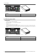
Image 4-1
Image 4-2
Order info:
Article No. Description
R9850960 D320 DVI input module
4.2 SDI input mod ule
Te chnical info:
• SDI data in.
• SDI loop through.
• 270Mbit/s transmission (SMP T E 259M-C).
• 525/625 interlaced.
• Coax (75 O hm).
• Amber LED ( upper LED on the front side) will be lit indicating recognition of film, either continuous or intermittent film detection.
• When placed in an input slot the green LED (lower LE D on the front side) will be lit indicating that the system ac knowledge the
module.
R5976388 D 320 DIGITIZER 0 5112002
11