PXL System User Manual Revised 3/14/2013
Table of Contents 1 Introduction 1 2 Safety Information 2 3 1. PXL System Overview 3 4 2. C-series Tile 4 2.1 Tile Overview 2.2 Installation Guidlines 2.3 Assembly & Mounting 2.3.1 Latches 2.3.2 Latch Adjustment 2.3.3 Center Mount 2.3.4 L-Bracket 2.4 Rigging Hardware 2.4.1 Stacked C-series Tiles 2.4.1.1 C-series Foot Support (430-0256) 2.4.1.2 C-series Pipe Clamp (430-0252) 2.4.2 Hanging C-series Tiles 2.4.2.1 Universal Header (430-0247) Detail 2.4.2.2 Universal Footer (430-0254) Detail 2.
.2 General Overview 4.2.1 Key Features 4.2.2 Safety Information 4.2.3 Hardware Overview 4.2.4 Power Up 4.3 Configuration and Operation 4.3.1 Vizomo Configuration 4.3.1.1 Software Installation 4.3.1.2 Vizomo Controller Overview 4.3.1.3 Blueprints 4.3.1.4 System Settings 4.3.1.5 Mapping 4.3.2 Video Mixer 4.3.2.1 Windowing Appendix A: Specifications Appendix B: Video File Encoding 7 5. Power and Data Distribution 5.0 Warnings 5.1 Hookup with a PXL Switch 5.2 PXL Switch Overview 5.3 Hookup with a PDB-5 5.
Introduction . 1 Home > Introduction Introduction revised 3/14/2013 6:34:47 PM Welcome to the PXL System manual. An overview of the complete system is given in Chapter 1, subsequent chapters provide greater detail on individual components. Version 4.6 Release Notes Vizomo: ● Support Barco PXL brightness sensor ● Added C11 brightness boost ● Further improved quality of scaled images ● Reverted improved gamma control RasterMAPPER: ● 4.
2 . Safety Information Home > Safety Information Safety Information WARNING Read the installation instructions before connecting the system to the power source. Attention: Avant de brancher le système sur la source d’alimentation, consulter les directives d’installation. Warnung: Vor dem Anschließen des Systems an die Stromquelle die Installationsanweisungen lesen. Safety Guidelines for Human Eyes WARNING The panels shall be mounted 15-20 meter from the viewing place, depending on the configuration.
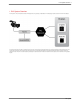
1. PXL System Overview . 3 Home > 1. PXL System Overview 1. PXL System Overview The PXL System is a family of components that consists of LED display devices, image processing, and data distribution. The following diagram provides a basic overview of how PXL is distributed. The Vizomo processor receives video data in a standard format such as DVI or SDI, and converts it to a special data format that may be used by the LED displays.
4 . 2. C-series Tile Home > 2. C-series Tile 2. C-series Tile The C-series tile is the primary building block of a modular system that may be used to construct large format video displays with arbitrary shapes. With resolutions in the range of 7-16mm pixel pitch, C-series tiles are suited to a wide variety of indoor and outdoor rental and architectural applications. The remainder of this chapter covers installation guidelines for C-series tiles.
2. C-series Tile .
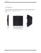
6 . 2. C-series Tile Home > 2. C-series Tile > 2.1 Tile Overview 2.1 Tile Overview C-series tiles are latched together along their edges to create large LED video displays with arbitrary shapes. Once a display shape has been decided upon, the display may be hung or attached to floor mounts for temporary rental applications, or permanently affixed to secondary steel in an architectural installation. Horizontally curved C-series displays may be created with radii varying from 4m convex to -10m concave.
2. C-series Tile . 7 Home > 2. C-series Tile > 2.2 Installation Guidlines 2.2 Installation Guidlines Rigging & Mounting Guidelines ● C11 and C8v C-series tiles have an IP66 rating and are suitable for use in most indoor and outdoor installations except where water immersion could occur. This conforms to the International Electrotechnical Commission (IEC) standard 60529. ● The C7 tiles have an IP50 rating and are suitable for indoor use only. ● Use caution when installing the display.
8 . 2. C-series Tile DANGER Risk of electrical shock. No user-serviceable parts inside. Observe all applicable electrical codes. The power outlet shall be installed near the equipment and shall be easily accessible. Do not hot plug any cables. Damage to the connector pins may occur. Resulting damage is not covered under warranty.
2. C-series Tile . 9 Home > 2. C-series Tile > 2.3 Assembly & Mounting 2.3 Assembly & Mounting The rear of a C-series tile contains the rigging hardware necessary for temporary hanging or stacking in a staging application, as well as hardware for permanent installation in an architectural setting. 1 2 3 4 5 6 7 8 9 Carrying handle. Folds away when not in use. Latch hook and lever. Locks multiple C-series tiles together. Power & data input. Combined AC power & data input via black PXL Cable socket.
10 . 2. C-series Tile Home > 2. C-series Tile > 2.3 Assembly & Mounting > 2.3.1 Latches 2.3.1 Latches There are a total of 8 integrated locking components on each tile as shown below; 4 latches and 4 catches. The photo below illustrates the optimal position of the handle and hook to allow for easy connection to other tiles. With the hook in this position and your thumbs slightly pushing on the open handle, you can hang one tile on another, then lock the tiles together.
2. C-series Tile . 11 Start with the latch fully open. Align the Cseries tiles so the latch of one aligns with the catch of the other. Place the latch hook in the catch. Ensure sure the hook is fully seated. Push the handle towards the catch. Ensure the hook is fully locked in the catch and that the safety is engaged. CAUTION Use light finger pressure when latching the tile. Do not force the lock handle.
12 . 2. C-series Tile Home > 2. C-series Tile > 2.3 Assembly & Mounting > 2.3.2 Latch Adjustment 2.3.2 Latch Adjustment The latches on a C-series tile can be adjusted to provide optimal connection between tiles. This adjustment moves the hook closer to or farther from the edge of the adjacent tile. The adjustment screws are located under the latch handle and require a 2mm hex key.
2. C-series Tile . 13 Home > 2. C-series Tile > 2.3 Assembly & Mounting > 2.3.3 Center Mount 2.3.3 Center Mount Center Mount Detail The center mount is used for attachment of vertical braces.
14 . 2. C-series Tile Home > 2. C-series Tile > 2.3 Assembly & Mounting > 2.3.4 L-Bracket 2.3.4 L-Bracket In addition to the Center Mount there are two M10 threaded holes in the back of each C-series tile that may be used for permanent mounting or attaching other accessories. The two threaded holes are located underneath the Center Mount. Removing the Center Mount Socket Use of the L-bracket require the removal of the center mount socket from the rear of the tile as described in the following steps.
2. C-series Tile . 15 The L-bracket allows adjustability along the X and Y axis.
16 . 2. C-series Tile CAUTION Use M10-16 bolts for the threaded mounting holes on the back of the C-series tile. Longer lengths will cause damage to the tile. Resulting damage is not covered under warranty.
2. C-series Tile . 17 Home > 2. C-series Tile > 2.4 Rigging Hardware 2.4 Rigging Hardware A variety of rigging hardware is available for deploying C-series displays. Headers are used for suspending displays from overhead, while feet are used for to create floor standing or "stacked" installations. Vertical pipe or truss are used to provide structure in stacked and heavy duty hanging configurations.
18 . 2. C-series Tile Home > 2. C-series Tile > 2.4 Rigging Hardware > 2.4.1 Stacked C-series Tiles 2.4.1 Stacked C-series Tiles This page illustrates a example of a stacked C-series system. Before placing an order for rigging equipment consult with a Barco representative to evaluate your specific needs. WARNING Vertical bracing for C-series tiles is for Z axis loading only. X and Y axis loads are carried by the C-series tiles themselves.
2. C-series Tile .
20 . 2. C-series Tile Home > 2. C-series Tile > 2.4 Rigging Hardware > 2.4.1 Stacked C-series Tiles > 2.4.1.1 C-series Foot Support (430-0256) 2.4.1.1 C-series Foot Support (430-0256) Top View: Side View: Dimensions are in inches.
2. C-series Tile . 21 Home > 2. C-series Tile > 2.4 Rigging Hardware > 2.4.1 Stacked C-series Tiles > 2.4.1.2 C-series Pipe Clamp (430-0252) 2.4.1.
22 . 2. C-series Tile Home > 2. C-series Tile > 2.4 Rigging Hardware > 2.4.2 Hanging C-series Tiles 2.4.2 Hanging C-series Tiles This page illustrates an example of a hanging C-series system. Before placing an order for rigging equipment consult with a Barco representative to evaluate your specific needs. NOTES: • One Universal Header supports max 25 tiles in height. • Based on application, lateral support may be needed.
2. C-series Tile . 23 Home > 2. C-series Tile > 2.4 Rigging Hardware > 2.4.2 Hanging C-series Tiles > 2.4.2.1 Universal Header (430-0247) Detail 2.4.2.1 Universal Header (430-0247) Detail 1 2 3 4 Machined 'Universal Header' chassis Chesebrough clamp - Truss mounting hardware Disk spring assembly - Load distribution mechanism Latch Catch - Socket for locking C-series panels to header. DANGER Do not hang more than 25 panels (10 m) tall with the integral rigging hardware.
24 . 2. C-series Tile Home > 2. C-series Tile > 2.4 Rigging Hardware > 2.4.2 Hanging C-series Tiles > 2.4.2.2 Universal Footer (430-0254) Detail 2.4.2.
2. C-series Tile . 25 Home > 2. C-series Tile > 2.5 Power & Data Distribution 2.5 Power & Data Distribution The C-series tiles receive power and data over a single daisy-chained PXL cable with color-coded male and female connectors. The length of the daisychain depends on the tile type - higher resolution tiles require shorter daisy-chains as discussed in chapter 5. Power and Data Distribution.
26 . 2.
2. C-series Tile . 27 Home > 2. C-series Tile > 2.5 Power & Data Distribution > 2.5.1 Tile Status Indicator 2.5.1 Tile Status Indicator The colored status indicator located on the back of the C-series tile allows you to easily monitor the state of each tile. Off No Power (Note: the status indicator remains black for a few seconds when the tile is first powered on) Optional.
28 . 2. C-series Tile Home > 2. C-series Tile > Notes: Beaufort Scale Notes: Beaufort Scale The following table is used as a reference for wind speed calculations throughout this guide.1 1. Beaufort scale, http://en.wikipedia.org/w/index.php?title=Beaufort_scale&oldid=303100822 (last visited July 20, 2009). 2.
2. C-series Tile . 29 Home > 2. C-series Tile > Notes: C-series Color Notes: C-series Color Additive Color Mixing Like TVs and computer screens, each pixel of a C-series display emits light. Because the LED pixels emit light, different colors are created additively; that is, the color of each pixel is created by mixing one or more primary colors together. This is in contrast with printed or painted images, which reflect light from a surface and use a subtractive color model.
30 . 2. C-series Tile The CIE 1931 XYZ color space lies within a horseshoe shaped locus on a two dimensional coordinate system. Points within the color space are uniquely defined with both an x and a y coordinate. These two values make up the "address" for a particular color. To find the yellow color referred to above, locate the intersection of x=0.42 and y=0.51 on the chart.
2. C-series Tile .
32 . 3. Helix P1 Home > 3. Helix P1 3. Helix P1 3.1 Installation Guidelines 3.2 Helix System Overview 3.3 Power & Data Distribution 3.
3. Helix P1 . 33 Home > 3. Helix P1 > 3.1 Installation Guidelines 3.1 Installation Guidelines ● Helix P1 pixel strings have an IP66 rating and are suitable for use in most indoor and outdoor installations except where water immersion could occur. This conforms to the International Electrotechnical Commission (IEC) standard 60529. ● Helix PXL Node Boxes have an IP65 rating and are suitable for use in most indoor and outdoor installations except where water immersion could occur.
34 . 3. Helix P1 Home > 3. Helix P1 > 3.2 Helix System Overview 3.2 Helix System Overview 3.2.1 Basic System Info 3.2.2 Helix P1 Pixel String Overview 3.2.
3. Helix P1 . 35 Home > 3. Helix P1 > 3.2 Helix System Overview > 3.2.1 Basic System Info 3.2.
36 . 3. Helix P1 Home > 3. Helix P1 > 3.2 Helix System Overview > 3.2.2 Helix P1 Pixel String Overview 3.2.2 Helix P1 Pixel String Overview Each Helix P1 pixel string has three parts: 1. Input Connector - this connects to the outputs on a PXL Node Box 2. Pixel Zero - a small power and data converter 3.
3. Helix P1 . 37 Home > 3. Helix P1 > 3.2 Helix System Overview > 3.2.3 PXL Node Box Overview 3.2.3 PXL Node Box Overview The PXL Node Box takes AC power and PXL data in, converts this to 24VDC and data out to four strings, and passes AC power and PXL data through to the next PXL Node Box. All connections are on one end panel of the box: 1. AC + PXL INPUT - black body - This uses the standard PXL Cable Connector. 2. AC + PXL OUTPUT - white body - This uses the standard PXL Cable Connector. 3.
38 . 3. Helix P1 Home > 3. Helix P1 > 3.3 Power & Data Distribution 3.3 Power & Data Distribution 3.3.1 Power & Data Overivew 3.3.2 Power Input 3.3.3 PXL Node Status Indicator 3.3.
3. Helix P1 . 39 Home > 3. Helix P1 > 3.3 Power & Data Distribution > 3.3.1 Power & Data Overivew 3.3.1 Power & Data Overivew The PDB-5 handles the power and data distribution for Helix P1 systems. All power & data cabling between the PDB-5 and PXL Node Boxes is done through integrated, cabling with color-coded male or female connectors. Alternative installations without a PDB-5 can make use of a break-in cable which accepts AC power and Ethernet data connections (P/N 350-0660).
40 . 3. Helix P1 Home > 3. Helix P1 > 3.3 Power & Data Distribution > 3.3.2 Power Input 3.3.2 Power Input Each PDB-5 has 2x 16 amp inputs and 6x 10 amp outputs with breakers for AC power distribution. The limit for each PDB-5 output is 10A, with a total output of 32A maximum per PDB-5. Refer to the PDB-5 User’s Guide for more information. Observe the following power guidelines when setting up your Helix P1 display: Max current draw of one PXL Node with four (4) P1 pixels strings is 0.
3. Helix P1 . 41 Home > 3. Helix P1 > 3.3 Power & Data Distribution > 3.3.3 PXL Node Status Indicator 3.3.3 PXL Node Status Indicator The status indicator located on the front of the PXL Node Box allows you to easily monitor the status of the node.
42 . 3. Helix P1 Home > 3. Helix P1 > 3.3 Power & Data Distribution > 3.3.4 Pixel Extension Cables 3.3.4 Pixel Extension Cables Helix P1 pixel strings can be located remotely from the PXL Node Box by using a Pixel Extension Cable. These are available in four lengths and can be combined together. Do not exceed 30m in total length from the PXL Node Box to the pixel string.
3. Helix P1 . 43 Home > 3. Helix P1 > 3.4 Helix P1 Assembly & Mounting 3.4 Helix P1 Assembly & Mounting PXL Node Box Mounting The PXL Node Box has six double-ended keyhole slots for mounting. The center hole is 8.5mm in diameter The slots are 4.5mm in diameter When used indoors the PXL Node Box may be mounted in any orientation.
44 . 3.
4. Vizomo . 45 Home > 4. Vizomo 4. Vizomo 4.1 Vizomo Quick Start Guides 4.2 General Overview 4.
46 . 4. Vizomo Home > 4. Vizomo > 4.1 Vizomo Quick Start Guides 4.1 Vizomo Quick Start Guides 4.1.1 Installing Vizomo Controller 4.1.2 Connecting with Vizomo Controller 4.1.3 Upgrading Vizomo 4.1.4 Mapping 4.1.5 Licensing 4.1.6 Adding and Playing Media 4.1.7 Capturing Video 4.1.
4. Vizomo . 47 Home > 4. Vizomo > 4.1 Vizomo Quick Start Guides > 4.1.1 Installing Vizomo Controller 4.1.1 Installing Vizomo Controller Vizomo Controller can be installed on any PC running Windows XP, Vista, or Windows 7 and is available from the Barco Creative LED support page: http://cled.barcousa.com NOTE: If a previous version of Vizomo Controller exists use add/remove programs in the Windows Control Panel to remove it.
48 . 4. Vizomo Home > 4. Vizomo > 4.1 Vizomo Quick Start Guides > 4.1.2 Connecting with Vizomo Controller 4.1.2 Connecting with Vizomo Controller When Vizomo Controller launches, the “Connect to processor” window opens listing processors found on your LAN. You can either select one of the processors listed or enter the IP address of another processor. Connect to processor window: After you select a processor, you need to log in with a user name and password.
4. Vizomo .
50 . 4. Vizomo Home > 4. Vizomo > 4.1 Vizomo Quick Start Guides > 4.1.3 Upgrading Vizomo 4.1.3 Upgrading Vizomo Vizomo upgrade files (labeled with a .vuz extension) can be downloaded from http://vizomo.com. There are two methods for transferring .vuz files to a Vizomo. 1. Vizomo Controller method 2. RasterMAPPER method 1. Vizomo Controller: On the System Settings page on the Files tab, press the Upgrade System button. A file browser will appear. Select the .vuz to be transferred to the Vizomo.
4. Vizomo . 51 Press Upgrade System to transfer a vuz file from the local computer running RasterMAPPER to the remote Vizomo. After the upgrade .vuz file is transferred, the upgrade automatically executes. If necessary the Vizomo will automatically restart.
52 . 4. Vizomo Home > 4. Vizomo > 4.1 Vizomo Quick Start Guides > 4.1.4 Mapping 4.1.4 Mapping Building and uploading maps for Vizomo is done with RasterMAPPER software available from Barco. For the quick start guide to RasterMAPPER, see the 6.4 RasterMAPPER QuickStart section.
4. Vizomo . 53 Home > 4. Vizomo > 4.1 Vizomo Quick Start Guides > 4.1.5 Licensing 4.1.5 Licensing Vizomos are all licensed when they are built. However, occasionally it becomes necessary to obtain a new license. The following steps describe the process of obtaining and loading a new license file. A Vizomo license is a unique text file that is loaded onto a Vizomo. A machine ID is required to generate a license for a Vizomo.
54 . 4. Vizomo Select the machine ID and another window will pop up from where the machine ID can be copied.
4. Vizomo . 55 Send the code to customer support with you new license request. Customer support can be reached at 866-374-7878. When you have a new license from customer support press the 'Upload License' button, navigate to your new license and select it for upload. When the license has been transfered to the remote Vizomo the Vizomo software will soft restart.
56 . 4. Vizomo 4.1.4 Mapping 4.1.6 Adding and Playing Media 4.1.7 Capturing Video 4.1.
4. Vizomo . 57 Home > 4. Vizomo > 4.1 Vizomo Quick Start Guides > 4.1.6 Adding and Playing Media 4.1.6 Adding and Playing Media If you are not yet familiar with the type of video content that best suits Vizomo, read Appendix B: Video File Encoding. Vizomo File formats: Motion Media The Vizomo processor can decode H264, MPEG, and MPEG-2 encoded video stored in the following container formats: ● Quicktime Movie (.mov) ● Windows Media (.
58 . 4. Vizomo 3. Navigate into the new folder and use the Send file(s) button to select/send the new file. 4. In the Video Mixer, the Reload Media Lists button needs to be pressed in order to see the new file(s) that were added.
4. Vizomo . 59 5. Select the new file for playback. 6. On the Main tab select Media to be the source. Content should now be playing.
60 . 4. Vizomo See also 4.1.1 Installing Vizomo Controller 4.1.2 Connecting with Vizomo Controller 4.1.3 Upgrading Vizomo 4.1.4 Mapping 4.1.5 Licensing 4.1.7 Capturing Video 4.1.
4. Vizomo . 61 Home > 4. Vizomo > 4.1 Vizomo Quick Start Guides > 4.1.7 Capturing Video 4.1.7 Capturing Video Capture formats vary by Vizomo model. See 4.2.3 Hardware Overview for a complete list of inputs and outputs by model type. The current, in production Vizomo models and capture formats are: L2i: HDMI The lower HDMI port on the capture card is the input port (circled in red below). Although the connector is HDMI the Vizomo capture card is not HDCP compliant.
62 . 4. Vizomo ● 1080p23.98 ● 1080p24 ● 1080p25 ● 1080p29.97 ● 1080p30 ● 1080i50 ● 1080i59.94 ● 1080i60 3. On the Vizomo blueprint Main tab, select Input as the source. 4. On the Vizomo blueprint Input tab, select HDMI and the appropriate resolution/frequency. NOTE: Some 720p sources are not compliant with the Vizomo capture cards. If 720p does not seem to be working try 1080p@30. SDI Hookup 1.
4. Vizomo . 63 2. Ensure the content is in one of the following resolutions and frequencies: 3. ● 480/29.98 NTSC ● 480/29.97 NTSC ● 576/25 PAL ● 720p50 ● 720p59.94 ● 720p60 ● 1080p23.98 ● 1080p24 ● 1080p25 ● 1080p29.97 ● 1080p30 ● 1080i50 ● 1080i59.94 ● 1080i60 On the Vizomo blueprint Main tab, select Input as the source. On the Vizomo blueprint Input tab, select SDI and set resolution config to auto-select or manually set the appropriate resolution/frequency. 4.
64 . 4. Vizomo NOTE: The Re-sync button will restart the capture interface in the event that a problem has occurred. See also 4.1.1 Installing Vizomo Controller 4.1.2 Connecting with Vizomo Controller 4.1.3 Upgrading Vizomo 4.1.4 Mapping 4.1.5 Licensing 4.1.6 Adding and Playing Media 4.1.
4. Vizomo . 65 Home > 4. Vizomo > 4.1 Vizomo Quick Start Guides > 4.1.8 Troubleshooting Choppy Video 4.1.8 Troubleshooting Choppy Video A problem you may encounter during configuration of a Vizomo is the bottom part of the tile not updating as frequently as the top (seen in the image below). Common Causes: 1. Vizomo PXL ports are not running at Gigabit ● Check Vizomo's Status page (see section 6.6.3 webUI) to confirm that all Vizomo PXL ports are running at Gigabit rates.
66 . 4. Vizomo See also 4.1.1 Installing Vizomo Controller 4.1.2 Connecting with Vizomo Controller 4.1.3 Upgrading Vizomo 4.1.4 Mapping 4.1.5 Licensing 4.1.6 Adding and Playing Media 4.1.
4. Vizomo . 67 Home > 4. Vizomo > 4.2 General Overview 4.2 General Overview The Vizomo video processor is an advanced LED screen controller. Unsurpassed flexibility and configurability, together with the most advanced video processing technology available, conquers virtually any creative or technical challenge. Use the built-in set of tools to create intricate visual arrangements with real-time video streams. Massive computational power ensures smooth content delivery to your LED screen.
68 . 4. Vizomo Home > 4. Vizomo > 4.2 General Overview > 4.2.1 Key Features 4.2.1 Key Features Raster MAPPER A simple TCP/IP connection between a computer running Raster MAPPER 4.5.0 and a Vizomo processor gives full remote control of multiple processors. A streamlined workflow provides one interface for mapping, PXL addressing, and screen control. Scaling Size multiple simultaneous windows with pixel-for-pixel accuracy.
4. Vizomo . 69 Home > 4. Vizomo > 4.2 General Overview > 4.2.2 Safety Information 4.2.2 Safety Information WARNING ● Keep connections free of stress to ensure proper operation. ● Do not open the Vizomo chassis, as there is risk of electric shock. ● Do not move the chassis while in operation. Internal components are susceptible to damage caused by vibration during operation. ● Do not block front or rear vents/fans to prevent overheating and/or damage. ● Do not place liquids on or around the unit.
70 . 4. Vizomo Home > 4. Vizomo > 4.2 General Overview > 4.2.3 Hardware Overview 4.2.3 Hardware Overview This page helps to identify the various types of Vizomo processors and their capabilities. Currently in Production L2i (530-0319) Front Items: On the locking door: ● Product model name ● IP Address label ● Model number label ● Serial number barcode Behind the door: ● Power on switch ● Reset switch ● 2 x USB 1.2/2.
4. Vizomo . 71 ● 1 x DVI over HDMI connector input (SMPTE 125M, SMPTE 170M, ITU-R BT.656-4, SMPTE 296M-2001, SMPTE 274M-2005) R2i (R9052942) Front Items: On the locking door: ● Product model name ● IP Address label ● Model number label ● Serial number barcode Behind the door: ● Power on switch ● Reset switch ● 2 x USB 1.2/2.
72 . 4. Vizomo Rear Connections: Power Input: IEC-C14 100-240V 50/60Hz 620W Data connections: ● 8 x USB 1.1/2.0 ● 2 x USB 3.0 ● 1 x PS2 ● 4 x PXL outputs on dual 10/100/1000Mbps ethernet ports ● 1 x User Port on a dual 10/100/1000Mbps ethernet port ● 1 x Factory Port on a dual 10/100/1000Mbps ethernet port ● 1 x DVI monitoring output ● 1 x DVI over HDMI connector input (SMPTE 125M, SMPTE 170M, ITU-R BT.
4. Vizomo . 73 Rear Connections: Power Input: IEC-C14 100-240V 50/60Hz 750W Data connections: ● 6x USB 1.1/2.0 ● 1 x PS2 ● 4 x PXL outputs on dual 10/100/1000Mbps ethernet ports ● 1 x User Port on a dual 10/100/1000Mbps ethernet port ● 1 x Factory Port on a dual 10/100/1000Mbps ethernet port ● 1 x DVI monitoring output ● 1 x DVI over HDMI connector input (SMPTE 125M, SMPTE 170M, ITU-R BT.656-4, SMPTE 296M-2001, SMPTE 274M-2005) ● 1 x HD-SDI input (SMPTE 125M, SMPTE 170M, ITU-R BT.
74 . 4. Vizomo Home > 4. Vizomo > 4.2 General Overview > 4.2.4 Power Up 4.2.4 Power Up Follow the steps below to power up the processor: 1. Attach the included IEC-C13 power cord to the unit via the IEC-C14 socket. 2. Plug the other end of the cord into a grounded 100-240V power source. 3. Attach any other cables that are relevant to your setup. 4. Ensure the power switch of the PSU is in the ON position. 5. Press the Vizomo's power switch on the front of the unit behind the locking door. 6.
4. Vizomo . 75 Home > 4. Vizomo > 4.3 Configuration and Operation 4.3 Configuration and Operation Overview Vizomo processors are configured over a network connection via two different client applications, RasterMAPPER and Vizomo Controller. RasterMAPPER is responsible for initial setup, including creating maps and setting operating parameters. Vizomo Controller is then used for configuring windowing, media selection, and file management.
76 . 4. Vizomo Home > 4. Vizomo > 4.3 Configuration and Operation > 4.3.1 Vizomo Configuration 4.3.1 Vizomo Configuration The following sections will cover: 4.3.1.1 Software Installation 4.3.1.2 Vizomo Controller Overview 4.3.1.3 Blueprints 4.3.1.4 System Settings 4.3.1.
4. Vizomo . 77 Home > 4. Vizomo > 4.3 Configuration and Operation > 4.3.1 Vizomo Configuration > 4.3.1.1 Software Installation 4.3.1.1 Software Installation Vizomo Controller can be installed on any PC running Windows XP, Vista, or Windows 7 and is available from the Barco Creative LED support site. NOTE: If a previous version of Vizomo Controller exists use add/remove programs in the Windows Control Panel to remove it.
78 . 4. Vizomo Home > 4. Vizomo > 4.3 Configuration and Operation > 4.3.1 Vizomo Configuration > 4.3.1.2 Vizomo Controller Overview 4.3.1.2 Vizomo Controller Overview When Vizomo Controller launches, the “Connect to processor” window opens listing processors found on your LAN. You can either select one of the processors listed or enter the IP address of another processor.
4. Vizomo . 79 The various parts of Vizomo Controller may be navigated using the bar to the right of the window.
80 . 4. Vizomo Home > 4. Vizomo > 4.3 Configuration and Operation > 4.3.1 Vizomo Configuration > 4.3.1.3 Blueprints 4.3.1.3 Blueprints A "blueprint" is a control script for the media engine of the Vizomo processor. A stock Vizomo has only one blueprint, the Video Mixer. The blueprint chooser can be used to re-load the current blueprint if necessary.
4. Vizomo . 81 Home > 4. Vizomo > 4.3 Configuration and Operation > 4.3.1 Vizomo Configuration > 4.3.1.4 System Settings 4.3.1.4 System Settings File Management The file management interface consists of action buttons on the left and a file browser on the right. At the topmost level of the file browser the folders have the names of all of the different categories of files available (e.g., media).
82 . 4. Vizomo Home > 4. Vizomo > 4.3 Configuration and Operation > 4.3.1 Vizomo Configuration > 4.3.1.5 Mapping 4.3.1.5 Mapping The remainder of Vizomo setup, including mapping, is accomplished with the RasterMAPPER utility. Please see chapter 6: RasterMAPPER for details.
4. Vizomo . 83 Home > 4. Vizomo > 4.3 Configuration and Operation > 4.3.2 Video Mixer 4.3.2 Video Mixer The Video Mixer Blueprint is the mechanism by which content is controlled in Vizomo. The Video Mixer Blueprint consists of three tabs; Main, Input, and Media. These tabs contains the controls to manage image playback and captured input. The selected content can be scaled with three possible windows.
84 . 4. Vizomo The Vizomo R1i unit has two video inputs to allow for HDMI and SDI capture. Only one active input should be connected at any given time. Media Tab To play a file, select from the folder/file selection window.
4. Vizomo . 85 When new media has been loaded press the Reload Media Lists button to see the changes. (see section 4.1.6 Adding Media to learn how to load content) Auto Advance To play all of the media in a selected folder in succession, enable Auto Advance by selecting the checkbox at the bottom of the Media tab. ● Vizomo will play each piece of video media for the duration of the clip. ● Vizomo will play still media for 5 seconds.
86 . 4. Vizomo Home > 4. Vizomo > 4.3 Configuration and Operation > 4.3.2 Video Mixer > 4.3.2.1 Windowing 4.3.2.1 Windowing In order to create a window, enable windows with the checkbox. Next, define the original size and position of content with the Source Rectangle controls... ...next, define the new size and position of content with the Destination Rectangle controls.
4. Vizomo . 87 Keep in mind the following points about source and destination windows: ● The source for a window needs to be within the boundaries of the media. ● A value of zero for the source width and height will result in an automatic selection of the entire source. ● Differences in source versus destination size results in automatic scaling. ● Windows can overlap sources and destinations.
88 . 4. Vizomo See the processor geometry section in 6.6.2 Setup Inspectors for the canvas size controls.
4. Vizomo . 89 Unity Scale Destination Offset: • Set Source Rectangle to 0,0. • Set Destination Rectangle to the content’s native width and height.
90 . 4. Vizomo Scale Up: • Set Source Rectangle to 0,0. • Set Destination Rectangle to the desired width and height.
4. Vizomo . 91 Scale Down: • Set Source Rectangle to 0,0. • Set Destination Rectangle to the desired width and height.
92 . 4. Vizomo Unity Scale Cropped Source: • Set Source Rectangle to desired size. • Set Destination Rectangle to the same size as the Source Rectangle.
4. Vizomo .
94 . 4. Vizomo Home > 4. Vizomo > Appendix A: Specifications Appendix A: Specifications PXL outputs ● Vizomo R1i / R2i: 4 PXL outputs ● Vizomo L1i / L2i: 1 PXL output Dimensions ● Vizomo R1i / R2i: 4U 19" rack chassis (480 x 178 x 618 mm) ● Vizomo L1i: 2U 19" rack chassis (480 x 88.
4. Vizomo . 95 ● 1080p30 ● 1080i50 ● 1080i59.
96 . 4. Vizomo Home > 4. Vizomo > Appendix B: Video File Encoding Appendix B: Video File Encoding Video files must be encoded and saved in a specific format and file naming structure for playback on a Vizomo processor. This section outlines the simple steps to convert your source material to a Vizomo-compatible format (H.264, MPEG-4 Part 10) and file name. Requirements: QuickTime Player with Pro License, v7.5.0 or later (Mac or PC) For more information go to: http://www.apple.com/quicktime/pro/.
4. Vizomo . 97 7. Press the “Settings” button to open the Standard Video Compression Settings window: Standard Video Compression Settings Window: 8. Confirm the following settings. 9. Press the “OK” button to return to the Movie Settings window. 10. Press the “Size” button to open the Export Size Settings window and confirm the dimen- sions for your output size are correct. Export Size Settings Window: 11. If your source footage is interlaced, be sure to check the “Deinterlace Source Video” checkbox.
98 . 4. Vizomo your video. When the encoding process is finished, you will have a new file with the proper codec, bit rate, and file name for playback on Vizomo processor. For information on transferring files to the Vizomo processor for playback, see File Management. For information on playing back video files, see Newly added blueprints are not displayed until the list has been manually rebuilt by pressing the ‘Reload Blueprints’ button. See File Management for information on adding new Blueprints.
5. Power and Data Distribution . 99 Home > 5. Power and Data Distribution 5. Power and Data Distribution For rental and staging applications, using the integrated power and data distribution of a PDB-5 is recommended (configuration on the left). For fixed installations, it may be preferable to use a Cisco 2960G network switch and external power distribution instead of PDB-5 power injectors (configuration on the right). Both configurations are described in this section.
100 . 5. Power and Data Distribution Home > 5. Power and Data Distribution > 5.0 Warnings 5.0 Warnings WARNING ● Read these instructions. ● Keep these instructions. ● Heed all warnings. ● Follow all instructions. ● Do not use this apparatus near water. ● Clean only with dry cloth. ● Do not block any ventilation openings. Install in accordance with the manufacturer’s instructions.
5. Power and Data Distribution . 101 Home > 5. Power and Data Distribution > 5.1 Hookup with a PXL Switch 5.1 Hookup with a PXL Switch The image below illustrates the data flow of a C-series system from image capture to tile using a PXL switch for data and power routing. Connections Checklist ● DVI over HDMI or SDI (to a R1i only) signal connected to Vizomo capture card ● Network cable from a Vizomo PXL output to a switch PXL input ● Break-in cable from switch PXL output to tiles.
102 . 5.
5. Power and Data Distribution . 103 Home > 5. Power and Data Distribution > 5.2 PXL Switch Overview 5.2 PXL Switch Overview For fixed installations, it may be preferable to use a Cisco 2960G network switch and external power distribution instead of PDB-5 power injectors. Preconfigured 8 and 24 port switches are available from Barco (P/N 420-0147 and 420-0146).
104 . 5.
5. Power and Data Distribution . 105 Home > 5. Power and Data Distribution > 5.3 Hookup with a PDB-5 5.3 Hookup with a PDB-5 The image below illustrates the data flow of a C-series system from image capture to tile using a PDB5 for data and power routing. Observe the following data limits when setting up your C-series display.
106 . 5. Power and Data Distribution Home > 5. Power and Data Distribution > 5.4 PDB-5 Overview 5.4 PDB-5 Overview The PDB-5 has been designed primarily for rental and staging applications. The PDB-5 handles the power and data distribution for C-series tiles and P1 nodes. 1. System Status Indicator. Indicates power and boot status. 2. Circuit Breakers. 2-pole, 10A magnetic hydraulic circuit breakers for each of the 6 PXL cable outputs. 3. Power Input B Indicator.
5. Power and Data Distribution .
108 . 5. Power and Data Distribution Home > 5. Power and Data Distribution > 5.5 PDB-5 Input & Output 5.5 PDB-5 Input & Output Connections Checklist ● DVI over HDMI or SDI (to a R1i only) signal connected to Vizomo capture card ● 100-240 50/60 VAC power to Vizomo ● PXL data cable from a Vizomo to the PXL Data Input jack on the back of the PDB-5. ● Power and data cable(s) from the fixture(s) to the appropriate PXL Cable output(s) on the back of the PDB-5.
5. Power and Data Distribution . 109 WARNING - Do not hot plug any cables. Damage to the connector pins may occur. Resulting damage is not covered under warranty. Observe the following power guidelines when setting up your C-series display. The tables below indicate maximum power consumption. C7 Max Power = 100 watts (@2,000 nits, full white) Voltage Max Panels per PDB52w/ 1 x 16A input Max Panels per PDB52w/ 2 x 16A input 240VAC 23 46 220VAC 21 42 208VAC 20 78 200VAC 19 75 1.
110 . 5. Power and Data Distribution Voltage Max Panels per PDB-52 w/ 1 x 16A input Max Panels per PDB-52 w/ 2 x 16A input 240VAC 45 90 220VAC 41 83 208VAC 39 200VAC 38 78 75 1. PDB-5 has 32A limit (2x 16A). 2. Maximum C11 panels per PDB-5 Port is 16. C8v Max Power = 55 watts (@8,000 nits, full white) Voltage Max Panels per PDB-52 w/ 1 x 16A input Max Panels per PDB-52 w/ 2 x 16A input 240VAC 70 140 220VAC 64 128 208VAC 61 200VAC 58 122 116 1. PDB-5 has 32A limit (2x 16A). 2.
5. Power and Data Distribution . 111 Home > 5. Power and Data Distribution > 5.2 Cables & Connectors 5.2 Cables & Connectors PXL Cable PXL cables are designed to carry both power and data, and are available in a variety of lengths to span the distance from a PDB-5 or switch to the display, as well as between each tile within the display. The gender of a PXL cable connector is determined by the power pins (the 3 large pins), each cable has a male and a female connector.
112 . 5. Power and Data Distribution Break-In Cable - Standard (P/N 350-0660) 1. Data Input - PXL data input via Neutrik EtherCon (RJ45) connector. 2. Power Input - AC power input via IEC C14 (male) connector. 3. Power and Data Output - Combined power and data via black female PXL cable connector. Break-In Cable - Fixed Install (P/N 350-0663) 1. Data Input - PXL data input via Ethernet (RJ45) connector. 2. Power Input - Unterminated AC power harness to be hardwired in fixed installations.
5. Power and Data Distribution . 113 1. Power and Data Input (Male) - Combined power and data via PXL cable connector. 2. Power Output - AC power output via IEC C13 (female) connector. 3. Data Output - PXL data output via Neutrik EtherCon (RJ45) connector. Break-Out Cable - Fixed Install (P/N 350-0678) 1. Power and Data Input (Male) - Combined power and data via PXL cable connector. 2. Power Output - Unterminated AC power harness to be hardwired in fixed installations.
114 . 6. RasterMAPPER Home > 6. RasterMAPPER 6. RasterMAPPER RasterMAPPER is a Windows and Apple OS X application used for mapping C-series tiles to the Vizomo processor and for making settings to remote Vizomo processors. The latest version of RasterMAPPER can be downloaded from http://vizomo.com 6.1 Software Installation 6.2 Basic Workflow 6.3 RasterMAPPER QuickStart Guides 6.4 UI Overview 6.5 Mapping 6.6 Processor Control 6.
6. RasterMAPPER . 115 Home > 6. RasterMAPPER > 6.1 Software Installation 6.1 Software Installation System Requirements RasterMAPPER software requires the following: ● Microsoft Windows® XP or ● Mac OS X v10.5+, Intel Processor (PowerPC not supported) with ● 1024 x 768 display (or larger), • 10 MB of disk space minimum • an ethernet port (to connect to a Vizomo processor) Download/Install Info Follow the steps below to install and run RasterMAPPER: Windows 1.
116 . 6. RasterMAPPER Home > 6. RasterMAPPER > 6.2 Basic Workflow 6.2 Basic Workflow RasterMAPPER has two main functions: ● Create a map which defines the relationship between pixels from the video source and the actual pixels on the modular LED fixtures. After creating the map in RasterMAPPER it is uploaded and stored on the processor. ● Control and adjust the processor as needed.
6. RasterMAPPER . 117 Home > 6. RasterMAPPER > 6.3 RasterMAPPER QuickStart Guides 6.3 RasterMAPPER QuickStart Guides The following basic information will get you up and running quickly with RasterMAPPER version 4.0 and greater. The steps detailed below are only those necessary to create a map, send it to the processor, and ensure the fixtures are configured properly on the processor. These steps are based on the RasterMAPPER Basic Workflow using the Vizomo video processor and C11 fixtures. 6.3.
118 . 6. RasterMAPPER Home > 6. RasterMAPPER > 6.3 RasterMAPPER QuickStart Guides > 6.3.1 Mapping 6.3.1 Mapping The mapping step is necessary to tell the Vizomo the relationship between pixels in the input signal, and where those pixels are located on the modular LED fixtures. This is accomplished by building a map of fixtures in a space representing the input pixels. Create and Send Map 1. Download and Install RasterMAPPER. 2. Launch RasterMAPPER.
6. RasterMAPPER . 119 5. Select a processor. 6. Select Save To... from the File menu . 7. Name the map and click Send Map to send the map to the Vizomo. NOTE: Each time a map on the Vizomo is changed perform the steps of 6.1.2 Enumeration and 6.1.3 Calibration.
120 . 6.
6. RasterMAPPER . 121 Home > 6. RasterMAPPER > 6.3 RasterMAPPER QuickStart Guides > 6.3.2 Enumeration 6.3.2 Enumeration The enumeration step associates fixtures in their physical cabled order with their logical position within the map. This is necessary to ensure that each fixture gets the correct video data that it needs to display an image when combined with all of it's neighbors. Failing to do this step may result in a display that has an image that is broken into randomly arranged squares.
122 . 6. RasterMAPPER 5. Check the status report to see activity during enumeration and the final outcome. 6. When the status area reads xxx nodes found, enumeration is complete click the Close button to close the window. NOTE: Each time a map on the Vizomo is changed perform the steps of 6.1.2 Enumeration and 6.1.3 Calibration.
6. RasterMAPPER . 123 Home > 6. RasterMAPPER > 6.3 RasterMAPPER QuickStart Guides > 6.3.3 Calibration 6.3.3 Calibration The calibration step is necessary to copy LED calibration data from each fixture back to the Vizomo processor, where the calibration algorithms are run. Failing to do this step may result in a speckled looking image, or fixtures that have a different color cast than their neighbors. Retrieve Calibration Data from PXL Fixtures 1. Click the Calibrate... button. 2.
124 . 6. RasterMAPPER 4. When the status area reads Complete, click the Close button to close the window. NOTE: Each time a map on the Vizomo is changed perform the steps of 6.1.2 Enumeration and 6.1.3 Calibration.
6. RasterMAPPER . 125 Home > 6. RasterMAPPER > 6.4 UI Overview 6.4 UI Overview OS X version of the RasterMAPPER user interface: Interface Sections The following illustrations identify the major sections of the RasterMAPPER user interface. Menu Bar Menus of common RasterMAPPER functions, including loading and saving map files, changing the view, and editing preferences.
126 . 6. RasterMAPPER Mode Selections Select views, processors, and operational modes. More detail is provided in section 6.3.1 Mode Selection.
6. RasterMAPPER . 127 Map Editing Everything for adding and editing of the fixtures on the map. More detail is provided in section 6.3.2 Map Editing.
128 . 6. RasterMAPPER Inspectors The Mapping/Setup buttons toggle this inspector pane between information about either the map or the selected processor. More detail is provided in sections 6.4.2 Mapping Inspectors and 6.5.2 Setup Inspectors.
6. RasterMAPPER .
130 . 6. RasterMAPPER Home > 6. RasterMAPPER > 6.4 UI Overview > 6.4.1 Mode Selection 6.4.1 Mode Selection The Mode selection region contains tools for the overall setup of the application. Map Title & Zoom Level At the top center of the application window the title of the map is displayed along with the current zoom level. Processor Select Select a processor from a drop down menu. Inspector Toggle The Setup/Mapping buttons toggle the inspector panels below.
6. RasterMAPPER . 131 Home > 6. RasterMAPPER > 6.4 UI Overview > 6.4.2 Map Editing 6.4.2 Map Editing The map editing section shows information about fixtures and provides the tools for making changes. Map Info Pane Shows port, sequence, XY coordinates and fixture type information for all fixtures in the map.
132 . 6. RasterMAPPER In the image above from the top down: ● Map Totals: Information about the current map ● Current Selection: Information about the selected fixture(s) ● The currently selected fixture is highlighted in the sequence list. ● Fixtures on hidden ports are displayed in gray. In the example above Port B is 'grayed out'. Note: Click on any fixture to highlight it both in the list and in the map view. Click the triangle to the left of a port or fixture to show or hide details.
6. RasterMAPPER .
134 . 6. RasterMAPPER Home > 6. RasterMAPPER > 6.5 Mapping 6.5 Mapping Mapping involves choosing existing fixtures or creating new ones and placing them on the work grid in the same order as they are cabled in the system. The processing equipment may contain multiple output ports for fixtures. Always be aware of which port fixtures are being assigned to. Additional functionality allows the changing of the wiring order of the fixtures in the map by re-sequencing. With RasterMAPPER Version 4.
6. RasterMAPPER . 135 Home > 6. RasterMAPPER > 6.5 Mapping > 6.5.1 Canvas 6.5.1 Canvas The work grid or canvas in RasterMAPPER is where you place fixtures. When you first launch RasterMAPPER, a blank canvas is displayed. Once you begin placing fixtures, they appear in a unique color. Fixtures on an inactive port are slightly transparent. Below are descriptions of the tools specific to the canvas. Select Tool The select tool highlights any fixture or group of fixtures on an active port.
136 . 6. RasterMAPPER release to select a fixture. Building the Map Click the map grid area to add the fixture to the map. Fixtures will be added to the selected port. Add fixtures to the canvas in the order they are wired (sequence). The sequence can be changed later, if desired (see Sequencing, p. 21 for more information). When placing fixtures, the x and y location is displayed adjacent to the cursor. The white square at the top left of each fixture aids in determining the fixture's Z rotation.
6. RasterMAPPER . 137 Home > 6. RasterMAPPER > 6.5 Mapping > 6.5.2 Mapping Inspectors 6.5.2 Mapping Inspectors The Mapping pane's inspectors are a collection of tools to help with map editing. Alignment Pane Use the buttons as the top of the alignment pane to align objects either Vertically or Horizontally. Select the fixtures or groups to be aligned and then press the button for the type of alignment desired.
138 . 6. RasterMAPPER The Duplicate Array inspector of the Layout tab displays the options for three Array Duplication modes. Grid Array 1. Enter the number of rows and columns the resulting array will be. 2. Choose the new scan order for the resulting array. 3. Enter the desired column and row offset between each duplicated array. RasterMAPPER automatically sets the offsets based on the width and height of the selected fixtures (objects), but you can enter your own, if desired.
6. RasterMAPPER . 139 desired. Circular Array ● Enter the total number of fixtures for the new array. ● Based on the count, the Separation angle and Fixture rotation will be automatically computed. ● Enter the desired Radius (in pixels) for the new array. Map Transfers Sending maps to Vizomo Select the Save to... menu item to open the Send Map window.
140 . 6. RasterMAPPER Send map window Name the map here and press Send Map to transfer the map to the Vizomo. Maps are sent to the processor selected in the Processor Select menu. Getting maps from Vizomo Select the Open Current Map menu item to retrieve a map from a remote Vizomo.
6. RasterMAPPER . 141 Home > 6. RasterMAPPER > 6.5 Mapping > 6.5.3 Sequencing 6.5.
142 . 6. RasterMAPPER Home > 6. RasterMAPPER > 6.5 Mapping > 6.5.4 Map Save/Open 6.5.4 Map Save/Open RasterMAPPER launches with a new, empty map. You can open existing maps and save the current map by using the File menu. NOTE: Don’t forget that in RasterMAPPER v4.0 and later you can have multiple maps open at the same time. This enables enhanced functionality like copying and pasting fixtures from one map to another.
6. RasterMAPPER . 143 Home > 6. RasterMAPPER > 6.5 Mapping > 6.5.5 Advanced Fixture Options 6.5.5 Advanced Fixture Options Creating Custom Fixtures RasterMAPPER provides a default list of PXL fixtures to use. You can also create new fixtures that can be saved with the current map or as a template fixture to be used with any map. If a custom fixture is created in a map and opened on another computer without that custom fixture, it will be automatically added to the current map. Select Edit this Menu...
144 . 6. RasterMAPPER Scan Order Click the Scan Order icon to select a scan order for the new fixture. Save to Map Saves the custom fixture to the current map. This fixture will not be loaded the next time RasterMAPPER is launched. However, if a map with a custom fixture is loaded, it will be placed in the Custom section of the fixture menu.
6. RasterMAPPER . 145 Fixtures can be duplicated both Horizontally and Vertically. 1. Choose Duplicate Horizontally from the Edit menu, or press Command + D(Mac), Control + D (Win) to place a copy of the fixture(s) on the canvas to the right of the selected fixture(s). If there is no space in the default location the duplicated fixture(s) will be placed in the next available area. 2.
146 . 6. RasterMAPPER Home > 6. RasterMAPPER > 6.6 Processor Control 6.6 Processor Control RasterMAPPER provides control over many functions on the Vizomo processor via the Configure Inspectors. Some parameters are sent instantly to the processor resulting in an immediate change. Other parameters are not sent until you expressly push a button or otherwise commit the changes. For more information on the Vizomo processor, please refer to the Vizomo User Guide.
6. RasterMAPPER . 147 Home > 6. RasterMAPPER > 6.6 Processor Control > 6.6.1 Processor List 6.6.1 Processor List RasterMAPPER provides the functionality to control different processors from the same interface. A processor select drop-down menu is presented at the top of the main program window and also displayed, when saving a map. Main Processor Select Edit Processor List To manually add a processor, select Edit Menu...
148 . 6. RasterMAPPER indicate OFFLINE. Remove Processor Highlight the processor to be removed and press the button with the - symbol Rename a Processor Edit a processor name by double clicking the name, click on the list when done.
6. RasterMAPPER . 149 Home > 6. RasterMAPPER > 6.6 Processor Control > 6.6.2 Setup Inspectors 6.6.2 Setup Inspectors Overview The inspectors in the Setup pane provide access to Vizomo processor functions. Most sections of the pane contain a triangle to the left of the section name allowing you to close or open that section. This gives you the flexibility to hide seldom used sections while ensuring frequently used ones remain visible.
150 . 6. RasterMAPPER See: 6.1.1 Enumeration for details Opens the Retrieve Calibration window. See: 6.1.2 Calibration for details Enables the status indicators on the rear of the C-series tiles Processor Geometry The Processor Geometry inspector pane: Specify the width and height of the Vizomo canvas manually or let Vizomo automatically set it based on the map (recommended). Below the Canvas size settings are the settings for the DVI output resolution and frequency.
6. RasterMAPPER . 151 Test pattern - Select from among 14 patterns. Use the checkbox to enable/disable. Brightness - Range is 0-1 defaults to 1 Gamma - Range is 1.0 to 3.0 defaults to 2.2 CCT - Range is 4000K to 10,000K defaults to 6,500K Gamut - Selections are; HDTV Rec 709, PAL, NTSC, Digital Cinema, Best Fit, C-Series. The default is C-Series.
152 . 6. RasterMAPPER Global tint - Ranges are 0 to 1.2 defaults to 1.0 Freeze and Blackout Freeze the current image on-screen while allowing playback and other functions to continue in the background. Blackout displays video black on the PXL output, all playback and other functions continue as normal in the background.
6. RasterMAPPER . 153 Home > 6. RasterMAPPER > 6.6 Processor Control > 6.6.3 webUI 6.6.3 webUI The Vizomo webUI is a web based User Interface that contains information about the system and other advanced features such as Vizomo's command line interface.
154 . 6. RasterMAPPER Overview >> PXL Nodes The PXL nodes page displays current information about the status of nodes (tiles). At the bottom of the page a download button allows for this information to be saved as a csv file. Advanced >>Console The console page is a tool for advanced users. Here, text commands are used to control a Vizomo. In the example below the brightness property is queried with the command '? system.output.pxl.fps'. The Vizomo responded with the current frame rate.
6. RasterMAPPER . 155 System >> Support The Support page contains a detailed summary of the system. It automatically updates every 10 seconds. The 'Download Support File' button at the bottom can be used to download the whole report as a file that can be emailed to customer support.
156 . 6. RasterMAPPER System >> Log The log page displays the full system log. System >> Configuration Some of the Vizomo parameters can be adjusted on the configuration page of the webUI. For the full set of controls use the RasterMAPPER interface. System >> Upgrade Transfer .vuz files to a remote Vizomo in order to perform an upgrade. System >> Shutdown Reboot or shutdown the Vizomo with the buttons on this page.
6. RasterMAPPER . 157 2. The IP address(s) of the Vizomo 3. The Barco.
158 . 6. RasterMAPPER Home > 6. RasterMAPPER > 6.7 Software Update 6.7 Software Update RasterMAPPER automatically checks for software updates when it is started. Update checks may also be manually triggered with the Check for Updates... function: RasterMAPPER Version 4.0 and newer includes automatic software upgrade functionality. If a new version is available, it can be downloaded and installed automatically. Automatic update settings can be managed in the preferences window.
6. RasterMAPPER .
160 . 6. RasterMAPPER Home > 6. RasterMAPPER > Appendix A: Notes Appendix A: Notes Typographic Information This User’s Guide uses the following typographic conventions: ● menu items are displayed in Bold Italics ● clickable buttons are displayed in Bold Title Case.
7. Change Log . 161 Home > 7. Change Log 7. Change Log PXL System 4.6 C-series / Helix Firmware: ● No changes Vizomo: ● Support Barco PXL brightness sensor ● Added C11 brightness boost ● Further improved quality of scaled images ● Reverted improved gamma control RasterMAPPER: ● Vizomo 4.6 compatibility PXL System 4.5 C-series / Helix Firmware: ● Improved bulk transfer speed (calibration, firmware) ● Fixed issue with downgrading below 4.
162 . 7. Change Log ● C7 support ● Auto-complete for web console ● Improved gamma control ● Added detection of unrecognized tiles ● Make use of new nVidia EDID mechanism to force DVI-D resolutions RasterMAPPER v4.4.1: ● Maps can now be retrieved from Vizomos ● C7 support ● Improved network connection to Vizomo ● Improved Vizomo UI PXL System 4.3 Vizomo v4.3.0: ● Enumerate on all four PXL ports ● Make use of tile PWM brightness control ● Improved network awareness ● RasterMAPPER v4.
7. Change Log . 163 C-series / Helix Firmware: ● C-series 'On Screen Enumeration', sequence numbers are now displayed during enumeration ● Improved PXL error handling Vizomo: ● New Video Mixer blueprint.
164 . 8. PXL System Online Help Notes Home > 8. PXL System Online Help Notes 8. PXL System Online Help Notes C-series Online Help System Copyright © 2010 Barco, Inc. The Barco logo, Cobra®, Helix™, Vizomo™, RasterMAPPER™ and Versa® are trademarks of Barco, Inc. Other trademarks and trade names may be used in this document to refer to products by other entities. Barco, Inc. claims no proprietary interest in trademarks and trade names owned by others.
Index
PDF Back Cover .