
User Guide


8 © Copyright 2008 TAC All Rights Reserved. F-27197-4
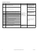
Additional Valve Sizing Information
For additional valve sizing information, see the
Vx-8xxx Selection Guide
, F-27199.
INSTALLATION
Inspection Inspect the package for damage. If damaged, notify the appropriate carrier immediately. If
undamaged, open the package and inspect the device for obvious damage. Return
damaged products.
Requirements • Tools (not provided): Wrenches.
• Training: Installer must be a qualified, experienced technician
• Appropriate accessories
Caution:
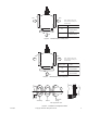
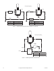
• Install the valve with the flow in the proper direction. See Figure-3 and Figure-4.
• Do not exceed the ratings of the device.
• Avoid locations where excessive moisture, corrosive fumes, or vibration are present.
Mounting 1. The valve should be mounted in a weather-protected area in a location that is within the
ambient limits of the actuator. When selecting a location, allow sufficient room for valve
linkage, actuator, and other accessories and for service of the product.
2. The preferred mounting position for the valve is with the valve stem vertical above the
valve body. Avoid mounting the valve so that the valve stem is below horizontal.
3. Pipe the valves with two inlets (“A” and “B” ports) and one outlet (“AB” port) for mixing
applications. Pipe with one inlet ("AB") and two outlets ("A" and "B") for diverting
applications. See Figure-3 and Figure-4.
Note:
“AB” is the valve’s bottom port. A label on the side of the valve provides port
identification.
Flanged Valve Bodies
The VB-8303-0-5-P series flanged valve bodies conform to ANSI B16.1 Class 125. The
companion flanges (not provided) should be the same specification as the valve. The 125
psi flanges have plain flat faces and should not be bolted to a raised faced flange.
1. All parts should be clean to assure tight seals.
2. The pipe with the companion flanges installed must be properly supported and aligned.
Be sure the companion flange is flush with the face of the valve body flange and lined
up squarely.
3. Use a gasket material (not provided) that is recommended for the medium being
handled.
Caution:
Do not apply pipe dope to the valve flange, gasket, or companion flange.
4. See Figure-5 for flange and flange bolt details. Figure-5 also shows the proper way a
flanged valve should be mounted.
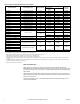
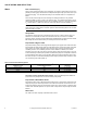
Table-5 Vapor Pressure of Water Table
Water Temp.
(°F)
Vapor
Pressure
(psia)
Water Temp.
(°F)
Vapor
Pressure
(psia)
Water Temp.
(°F)
Vapor
Pressure
(psia)
Water Temp.
(°F)
Vapor
Pressure
(psia)
40 0.12 90 0.70 140 2.89 190 9.34
50 0.18 100 0.95 150 3.72 200 11.53
60 0.26 110 1.28 160 4.74 210 14.12
70 0.36 120 1.69 170 5.99 220 17.19
80 0.51 130 2.22 180 7.51 230 20.78