
User Guide


6 © Copyright 2008 TAC All Rights Reserved. F-27197-4
VALVE SIZING AND SELECTION
Water Flow Coefficient (Cv)
Sizing a valve requires selecting a flow coefficient (C
v
), which is defined as the flow rate in
gallons per minute (gpm) of 60°F water that will pass through the fully open valve with a 1 psi
pressure drop (
Δp). It is calculated according to the formulas shown in “C
v
Equation for
Water”.
Since the flow rate through the heat exchanger is usually specified, the only variable
normally available in sizing a valve is the pressure drop. The following information can be
used to determine what pressure drop to use in calculating a valve C
v
. Using the calculated
C
v
, consult Table-4 or Table-5 to select the valve body with the nearest available C
v
.
Caution:
Be sure that the anticipated pressure drop across the valve will not exceed the
close-off pressure rating and the maximum pressure differential rating listed in the
Vx-8xxx
Selection Guide
, F-27199.
Two-position
Two-position control valves are normally selected “line size” to keep pressure drop at a
minimum. If it is desirable to reduce the valve below line size, then 10% of “available
pressure” (that is, the pump pressure differential available between supply and return mains
with design flow at the valve location) is normally used to select the valve.
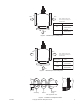
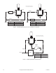
Proportional to Bypass Flow
Proportional mixing valves used to bypass flow (Figure-6) are piped on the outlet side of the
load to throttle the water flow through the load and therefore control heat output of the load.
These valves are usually selected to take a pressure drop equal to at least 50% of the
“available pressure.” As “available pressure” is often difficult to calculate, the normal
procedure is to select the valve using a pressure drop at least equal to the drop in the coil
or other load being controlled (except where small booster pumps are used) with a minimum
recommended pressure drop of 5 psi (34 kPa). When the design temperature drop is less
than 60°F (33°C) for conventional heating systems, higher pressure drops across the valve
are needed for good results (Table-3).
Secondary Circuits with Small Booster Pumps: 50% of available pressure difference
(equal to the drop through load, or 50% of booster pump head).
Proportional to Blend Water Flows
Proportional valves used to blend two water flows (Figure-7 and Figure-8) control the heat
output by varying the water temperature to the load at constant flow. These valves do not
require high pressure drops for good control results. They can be sized for a pressure drop
of 20% of the “available pressure” or equal to 25% of the pressure drop through the load at
full flow.
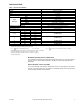
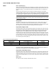
Water Table
See Table-4 for water capacity of VB-8303 series valves.
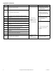
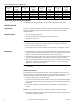
Table-3 Conventional Heating System
Design Temperature
Load Drop °F (°C)
Recommended Pressure Drop
a
(% of Available Pressure)
a
Recommended minimum pressure drop = 5 psi (34 kPa).
Multiplier on
Load Drop
60 (33) or More 50% 1 x Load Drop
40 (22) 66% 2 x Load Drop
20 (11) 75% 3 x Load Drop