
User Guide


F-27197-4 © Copyright 2008 TAC All Rights Reserved. 3
SPECIFICATIONS
Maximum Operating Pressure Differential
The maximum operating pressure differential is dependent on the size of the valve and the
actuator. See the
Vx-8xxx Selection Guide
, F-27199, for maximum operating pressure
differential.
Normal Position of Valve Assembly
For a valve assembly (valve, linkage, and actuator) to have a normal position, the actuator
must be of the spring return type. See Table-2 for compatible spring return and non-spring
return actuators and their normal positions.
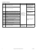
Table-1 Specifications/Models
Specifications Valve Body Series VB-8303-0-5-P
Service Chilled or Hot Water
Flow Characteristics (Figure-1) Modified Linear (May Be Piped as Mixing or Diverting)
Sizes 2-1/2" to 6"
Type of End Fitting 125 psi Flanged
Valve
Materials
Body Cast Iron
Seat Forged Brass
Stem Stainless Steel
Plug Forged Brass
Packing Spring-loaded TFE/EPDM
Seat Ring None
ANSI Pressure Class (Figure-2) 125 psi Flanged (up to 200 psig below 150°F)
Allowable Control Media Temperature 20 to 281 °F (-7 to 138 °C)
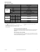
Close-off Pressure
a
a
Exceeding maximum close-off pressure voids product warranty. Do not exceed maximum operating pressure differential. See Vx-8xxx Selection Guide,
F-27199 for maximum operating pressure differentials.
35 psi (241 kPa)
Valve Size C
v
Rating
b
b
(where ΔP is measured in psi) k
vs
= C
v
/ 1.156 (where ΔP is measured in bar; 1 bar = 100 kPa)
k
vs
Rating
b
Complete Valve Body Part Number
2-1/2”
80
c
c
Mixing configuration. flow from either A or B to AB ports. See Figure-3 on page 9.
69
c
VB-8303-0-5-1295
d
d
Diverting configuration, flow AB to A ports. See Figure-4 on page 9.
82
d
115
e
e
Diverting configuration, flow AB to B ports. See Figure-4 on page 9.
99
e
3”
110
c
95
c
VB-8303-0-5-13120
d
104
d
120
e
104
e
4” 190
f
f
All flow configurations.
164
f
VB-8303-0-5-14
5" 290
f
251
f
VB-8303-0-5-15
6" 500
f
433
f
VB-8303-0-5-16
C
v
gpm
P
Δ
-----------=
k
vs
m
3
h
⁄
P
Δ
---------------
=