
User Guide

F-26076-2 © Copyright 2008 TAC All Rights Reserved. 5
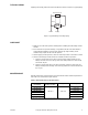
VALVE SIZING AND SELECTION
Water Two-position
Two-position control valves are normally selected “line size” to keep pressure drop at a
minimum. If it is desirable to reduce the valve below line size, then 10% of “available
pressure” (that is, the pump pressure differential available between supply and return mains
with design flow at the valve location) is normally used to select the valve.
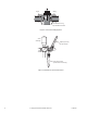
Proportional to Bypass Flow
Proportional valves used to bypass flow are piped on the inlet side of the load to throttle the
water flow through the load and therefore control heat output of the load. These valves are
usually selected to take a pressure drop equal to at least 50% of the “available pressure.”
As “available pressure” is often difficult to calculate, the normal procedure is to select the
valve using a pressure drop at least equal to the drop in the coil or other load being controlled
(except where small booster pumps are used) with a minimum recommended pressure drop
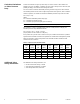
of 5 psi (34 kPa). When the design temperature drop is less than 60°F (33°C) for
conventional heating systems, higher pressure drops across the valve are needed for good
results (Table-3).
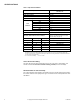
Table-3 Conventional Heating System.
Secondary Circuits with Small Booster Pumps: 50% of available pressure difference
(equal to the drop through load, or 50% of booster pump head).
Proportional to Blend Water Flows
Proportional valves used to blend two water flows control the heat output by varying the
water temperature to the load at constant flow. These valves do not require high pressure
drops for good control results. They can be sized for a pressure drop of 20% of the “available
pressure” or equal to 25% of the pressure drop through the load at full flow.
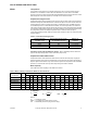
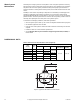
Water Capacity
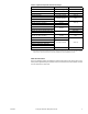
See Table-4 for water capacity of VB-7323 series valves.
Table-4 Water Capacity in Gallons Per Minute for VB-7323 Series.
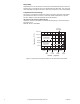
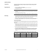
C
v
Equation
Where:
C
v
= Coefficient of flow
GPM = U.S. gallons per minute (60°F, 15.6°C)
ΔP = Differential pressure in psi (pressure drop)
Design Temperature
Load Drop °F (°C)
Recommended Pressure Drop
a
(% of Available Pressure)
Multiplier on
Load Drop
60 (33) or More 50% 1 x Load Drop
40 (22) 66% 2 x Load Drop
20 (11) 75% 3 x Load Drop
a
Recommended minimum pressure drop = 5 psi (34 kPa).
Valve Body
Part Number
C
v
Rating
Differential Pressure (
ΔP in psi)
12345678910152035
VB-7323-0-4-4 4.4 4.4 6.2 7.6 8.8 9.9 11 12 12 13 14 17 20 26
VB-7323-0-4-6 7.5 7.5 11 13 15 17 18 20 21 23 24 29 34 44
VB-7323-0-4-8 15 15 21 26 30 34 37 40 42 45 47 58 67 89
VB-7323-0-4-9 20 20 28 35 40 45 49 53 57 60 63 77 89 118
VB-7323-0-4-10 28 28 39 48 56 63 69 74 79 84 88 108 125 166
VB-7323-0-4-11 40 40 57 69 80 89 98 106 113 120 126 155 179 237
C
v
=
GPM
ΔP=
GPM
C
v
()
GPM = C
v
ΔP
2
ΔP