
User Guide
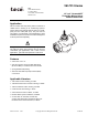
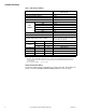
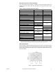
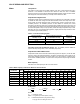
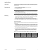
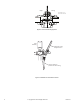
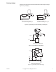
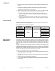
Table Of Contents
- Application
- VB-7313 series three-way mixing valves control hot or chilled water in heating or air conditioning systems. These valves must be...
- Danger: Do not use for combustible gas applications. The VB-7313 series valve packings are not rated for combustible gas applications, and if used in these applications, gas leaks and explosions could result.
- Features
- Applicable Literature
- . TAC Valve Products Catalog, F-27414
- . TAC Electric-Electronic Products Catalog, F-27382
- . TAC Pneumatic Products Catalog, F-27383
- . CA-28 Control Valve Sizing, F-13755
- . Valve Selection Chart for Water, F-11080
- . EN-205 Water System Guidelines, F-26080
- . Vx-7xxx-8xx, Vx-7xxx-59x, Vx-9xxx-8xx, Vx-9xxx-59x Globe Valve Assemblies with TAC DuraDrive Linear Series Actuators, F-26752
- SPECIFICATIONS
- VALVE SIZING AND SELECTION
- INSTALLATION
- Inspection
- Requirements
- Mounting
- 1. The valve should be mounted in a weather-protected area in a location that is within the ambient limits of the actuator. When...
- 1. Apply pipe dope sparingly to all but the last two threads of a properly threaded, reamed, and cleaned pipe. Make sure that pi...
- 2. Start the joint by hand screwing the pipe into the valve. If the thread engagement feels “right,” turn the pipe by hand as far as it will go.
- 3. Use a pipe wrench to fully tighten the valve to the pipe. Do not over tighten or strip threads. SeeTable-6 and Figure-3 for t...
- Table-6 Normal Thread Engagement Between Male Pipe Thread and Valve Body.
- Figure-3 Normal Thread Engagement.
- Figure-4 Installation of Screwed End Valves.
- TYPICAL PIPING
- CHECKOUT
- 1. Make sure the valve stem operates smoothly before installing the valve linkage and the actuator.
- 2. If the stem does not operate smoothly, it may indicate that the valve was twisted or crushed during installation or that the stem was bent by rough handling. These conditions may require that the valve be replaced.
- 3. After the piping is under pressure, check the valve body and the connections for leaks.
- 4. After the valve linkage and the actuator are installed, check their operation.
- a. Drive the actuator and run the valve to the stem down position. Make sure the linkage and valve stem move freely. At the stem down position, the valve should shut off the “B” port.
- b. Drive the actuator and valve to the stem up position. Again, the valve stem and linkage should operate smoothly. At the stem up position, the valve should shut off the “A” port.
- MAINTENANCE
- 1. Make sure the valve stem operates smoothly before installing the valve linkage and the actuator.
- DIMENSIONAL DATA

6 © Copyright 2007 TAC All Rights Reserved. F-26074-1
Cavitation Limitations
on Valve Pressure
Drop
A valve selected with too high a pressure drop can cause erosion of discs and/or wire
drawing of the seat. In addition, cavitation can cause noise, damage to the valve trim (and
possibly the body), and choke the flow through the valve.
Do not exceed the maximum differential pressure (pressure drop) for the valve selected.
The following formula can be used on higher temperature water systems, where cavitation
could be a problem, to estimate the maximum allowable pressure drop across the valve:
Pm = 0.5 (P
1
– Pv)
Where:
Pm = Maximum allowable pressure drop (psi)
P
1
= Absolute inlet pressure (psia)
Pv = Absolute vapor pressure (psia) (refer to Table-5)
Note: Add 14.7 psi to gauge supply pressure to obtain absolute pressure value.
For example, if a valve is controlling 200°F water at an inlet pressure of 18 psig, the
maximum pressure drop allowable would be:
Pm = 0.5 [(18 + 14.7) – 11.53] = 10.6 psi
(Vapor pressure of 200°F water is 11.53 psia.)
If the pressure drop for this valve is less than 10.6 psi, cavitation should not be a problem.
Systems where cavitation is shown to be a problem can sometimes be redesigned to provide
lower inlet velocities. Valves having harder seat materials should be furnished if inlet
velocities cannot be lowered.
Table-5 Vapor Pressure of Water Table.
Additional Valve
Sizing Information
For additional valve sizing information, see:
• CA-28 Control Valve Sizing, F-13755
• Valve Selection Chart Water, F-11080
Water
Temp.
(°F)
Vapor
Pressure
(psia)
Water
Temp.
(°F)
Vapor
Pressure
(psia)
Water
Temp.
(°F)
Vapor
Pressure
(psia)
Water
Temp.
(°F)
Vapor
Pressure
(psia)
40 0.12 90 0.70 140 2.89 190 9.34
50 0.18 100 0.95 150 3.72 200 11.53
60 0.26 110 1.28 160 4.74 210 14.12
70 0.36 120 1.69 170 5.99 220 17.19
80 0.51 130 2.22 180 7.51 230 20.78