
User Guide
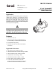
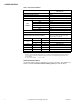
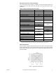
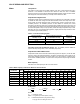
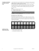
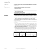
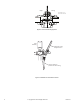
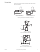
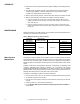
Table Of Contents
- Application
- VB-7313 series three-way mixing valves control hot or chilled water in heating or air conditioning systems. These valves must be...
- Danger: Do not use for combustible gas applications. The VB-7313 series valve packings are not rated for combustible gas applications, and if used in these applications, gas leaks and explosions could result.
- Features
- Applicable Literature
- . TAC Valve Products Catalog, F-27414
- . TAC Electric-Electronic Products Catalog, F-27382
- . TAC Pneumatic Products Catalog, F-27383
- . CA-28 Control Valve Sizing, F-13755
- . Valve Selection Chart for Water, F-11080
- . EN-205 Water System Guidelines, F-26080
- . Vx-7xxx-8xx, Vx-7xxx-59x, Vx-9xxx-8xx, Vx-9xxx-59x Globe Valve Assemblies with TAC DuraDrive Linear Series Actuators, F-26752
- SPECIFICATIONS
- VALVE SIZING AND SELECTION
- INSTALLATION
- Inspection
- Requirements
- Mounting
- 1. The valve should be mounted in a weather-protected area in a location that is within the ambient limits of the actuator. When...
- 1. Apply pipe dope sparingly to all but the last two threads of a properly threaded, reamed, and cleaned pipe. Make sure that pi...
- 2. Start the joint by hand screwing the pipe into the valve. If the thread engagement feels “right,” turn the pipe by hand as far as it will go.
- 3. Use a pipe wrench to fully tighten the valve to the pipe. Do not over tighten or strip threads. SeeTable-6 and Figure-3 for t...
- Table-6 Normal Thread Engagement Between Male Pipe Thread and Valve Body.
- Figure-3 Normal Thread Engagement.
- Figure-4 Installation of Screwed End Valves.
- TYPICAL PIPING
- CHECKOUT
- 1. Make sure the valve stem operates smoothly before installing the valve linkage and the actuator.
- 2. If the stem does not operate smoothly, it may indicate that the valve was twisted or crushed during installation or that the stem was bent by rough handling. These conditions may require that the valve be replaced.
- 3. After the piping is under pressure, check the valve body and the connections for leaks.
- 4. After the valve linkage and the actuator are installed, check their operation.
- a. Drive the actuator and run the valve to the stem down position. Make sure the linkage and valve stem move freely. At the stem down position, the valve should shut off the “B” port.
- b. Drive the actuator and valve to the stem up position. Again, the valve stem and linkage should operate smoothly. At the stem up position, the valve should shut off the “A” port.
- MAINTENANCE
- 1. Make sure the valve stem operates smoothly before installing the valve linkage and the actuator.
- DIMENSIONAL DATA

F-26074-1 © Copyright 2007 TAC All Rights Reserved. 5
VALVE SIZING AND SELECTION
Water Two-position
Two-position control valves are normally selected “line size” to keep pressure drop at a
minimum. If it is desirable to reduce the valve below line size, then 10% of “available
pressure” (that is, the pump pressure differential available between supply and return mains
with design flow at the valve location) is normally used to select the valve.
Proportional to Bypass Flow
Proportional valves used to bypass flow (Figure-5) are piped on the outlet side of the load
to throttle the water flow through the load and therefore control heat output of the load.
These valves are usually selected to take a pressure drop equal to at least 50% of the
“available pressure.” As “available pressure” is often difficult to calculate, the normal
procedure is to select the valve using a pressure drop at least equal to the drop in the coil
or other load being controlled (except where small booster pumps are used) with a minimum
recommended pressure drop of 5 psi (34 kPa). When the design temperature drop is less
than 60°F (33°C) for conventional heating systems, higher pressure drops across the valve
are needed for good results (
Table- 3 ).
Table-3 Conventional Heating System.
Secondary Circuits with Small Booster Pumps: 50% of available pressure difference
(equal to the drop through load, or 50% of booster pump head).
Proportional to Blend Water Flows
Proportional valves used to blend two water flows (Figure-6 and Figure-7) control the heat
output by varying the water temperature to the load at constant flow. These valves do not
require high pressure drops for good control results. They can be sized for a pressure drop
of 20% of the “available pressure” or equal to 25% of the pressure drop through the load at
full flow.
Water Capacity
See Tab l e - 4 for water capacity of VB-7313 series valves.
Table-4 Water Capacity in Gallons Per Minute for VB-7313 Series.
C
v
Equation
Where:
C
v
= Coefficient of flow
GPM = U.S. gallons per minute (60°F, 15.6°C)
ΔP= Differential pressure in psi (pressure drop)
Design Temperature
Load Drop °F (°C)
Recommended Pressure Drop
a
(% of Available Pressure)
Multiplier on
Load Drop
60 (33) or More 50% 1 x Load Drop
40 (22) 66% 2 x Load Drop
20 (11) 75% 3 x Load Drop
a
Recommended minimum pressure drop = 5 psi (34 kPa).
Valve Body
Part Number
C
v
Rating
Differential Pressure (ΔP in psi)
1 2 3 4 5 6 7 8 9 10 15 20 35
VB-7313-0-4-2 2.2 2.20 3.11 3.81 4.40 4.92 5.39 5.82 6.22 6.60 6.96 8.52 9.84 13.02
VB-7313-0-4-4 4.4 4.40 6.22 7.6 8.8 9.8 10.8 11.6 12.4 13.2 13.9 17.0 19.7 26.0
VB-7313-0-4-6 7.5 8.0 11.3 13.9 16.0 17.9 19.6 21.2 22.6 24.0 25.3 31.0 35.8 47
VB-7313-0-4-8 14 14 20 24 28 31 34 37 40 42 44 54 63 83
VB-7313-0-4-9 20 20 28 35 40 45 49 53 57 60 63 77 89 118
VB-7313-0-4-10 28 28 39 48 56 63 69 74 79 84 88 108 125 166
VB-7313-0-4-11 41 41 58 71 82 92 100 109 116 123 130 159 183 243
C
v
=
GPM
ΔP=
GPM
C
v
()
GPM = C
v
ΔP
2
ΔP