
User Guide

6 © Copyright 2008 TAC All Rights Reserved. F-24392-2
INSTALLATION
Inspection Inspect the package for damage. If damaged, notify the appropriate carrier immediately.
If undamaged, open the package and inspect the device for obvious damage. Return
damaged products.
Requirements • Training: Installer must be a qualified, experienced technician
• Appropriate accessories
Caution:
• Install the valve with the flow in the direction of the flow arrows (“A” and “B” ports are
the inlets and “AB” port is the outlet).
• Do not exceed the ratings of the device.
• Avoid locations where excessive moisture, corrosive fumes, or vibration are present.
Mounting 1. The valve should be mounted in a weather protected area in a location that is within the
ambient limits of the actuator. When selecting a location, allow sufficient room for valve
linkage, actuator, and other accessories and for service of the product.
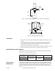
2. The preferred mounting position for the valve is with the valve stem vertical above the
valve body. Avoid mounting the valve so that the valve stem is below horizontal.
3. On steam applications where the ambient temperature approaches the limit of the
actuator, the valve stem should be mounted 45° from vertical.
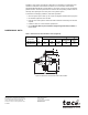
4. The VB-7312 series of flared valve bodies conform to SAE 45°. The valves must be
piped with two inlets (“A” and “B” ports) and one outlet (“AB” port).
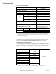
TYPICAL PIPING
All piping must comply with local codes and ordinances. Refer to Figure-3 through Figure-5
for typical piping.
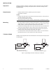
Figure-3 Typical Piping for Control of Heating or Cooling Coil.
Coil
Return
Bypass
Supply Supply
Coil
Bypass
Return
Stem down flow through coil.
Stem up flow through coil bypass.
Stem up flow through coil.
Stem down flow through coil bypass.
A
A
B
B
Valve
A
A
B
B
Valve