
Selection Guide


Schneider Electric 839 North Perryville Rd. Rockford, IL 61107 1-888-444-1311 www.schneider-electric.com
F-27649-2 September 2013
© 2013 Schneider Electric. All rights reserved.
VB-7200 Two-Way Globe Valve Bodies
Venta
9
A valve selected with too high a pressure drop can cause erosion of seals and/or wire drawing of the seat. In
addition, cavitation can cause noise, damage to the valve trim (and possibly the body), and choke the flow.
Do not exceed the maximum differential pressure (pressure drop) for the valve selected.
The following formula can be used on higher temperature water systems, where cavitation could be a
problem, to estimate the maximum allowable pressure drop across the valve:
Pm = 0.5 (P1 – Pv)
Where:
Pm = Maximum allowable pressure drop (psi)
P1 = Absolute inlet pressure (psia)
Pv = Absolute vapor pressure (psia)
Note: Add 14.7 psi to gauge supply pressure to obtain absolute pressure value.
For example, if a valve is controlling 200°F water at an inlet pressure of 18 psig, the
maximum pressure drop allowable would be:
Pm = 0.5 [(18 + 14.7) – 11.53] = 10.6 psi
(Vapor pressure of 200°F water is 11.53 psia)
If the pressure drop for this valve is less than 10.6 psi, cavitation should not be a problem.
Systems where cavitation is shown to be a problem can sometimes be adjusted to provide higher down-
stream back pressures. Valves having harder seat materials should be furnished if inlet velocities cannot
be lowered.
Vapor Pressure Of Water Table
Temp.
(°F)
Pressure
(psia)
Temp.
(°F)
Pressure
(psia)
Temp.
(°F)
Pressure
(psia)
Temp.
(°F)
Pressure
(psia)
40 0.12 90 0.70 140 2.89 190 9.34
50 0.18 100 0.95 150 3.72 200 11.53
60 0.26 110 1.28 160 4.74 210 14.12
70 0.36 120 1.69 170 5.99 220 17.19
80 0.51 130 2.22 180 7.51 230 20.78
Cavitation Limitations on Valve Pressure Drop
Seat Leakage Classes
ANSI/FCI 70-2
Leakage Class
Maximum Seat Leakage
Class II 0.5% of rated Cv
Class III 0.1% of Rated Cv
Class IV 0.01% of Rated Cv
Class V 0.0005 ml per minute per inch of orifice diameter per psi differential
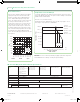
Water Capacity Graph Instructions
To Select the approproate valve Cv from the Graph:
1. Select the required flow from the “Flow in GPM” axis.
2. Select available pressure drop from the “Pressure Drop in psi” axis.
3. Select the appropriate line and follow to the Capacity Cv (Kv) listing to choose the closest valve Cv flow
coefficient.
4. Confirm the selection by calculation from the water equations (optional).
F-27649-1.indd 9 3/28/14 1:09 PM