
Selection Guide


Venta
4
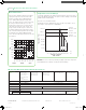
VB-7200 Two-Way Globe Valve Bodies
© 2012 Schneider Electric. All rights reserved.
Schneider Electric 839 North Perryville Rd. Rockford, IL 61107 1-888-444-1311 www.schneider-electric.com
F-27649-1 July 2012
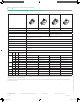
Product Selection: Brass Trim Soft Seat Union for Radiators and Other Applications
Two-Way Brass Trim Body Type Union Angle NPT Union Straight NPT Union Straight NPT Union Angle NPT
with Stainless Steel
Plug
Union Straight NPT
with Stainless Steel
Plug
Series Part Number VB-7211-0-3- VB-7211-0-4- VB-7221-0-4- VB-7251-0-3- VB-7251-0-4-
Pipe Sizes 1/2” to 1-1/4”
Stem Action Up Open Up Open Up Closed Up Open Up Open
ANSI Pressure Class 250 psi (up to 400 psig below 150°F)
ANSI Seat Leakage ANSI IV
d
Designed to ANSI V with ANSI IV above 35 psi
(241 kPa) close off. Long term seat leakage
dependent on proper water conditioning
maintenance of the system.
ANSI IV
d
Control Media and Temperature 20 to 281°F (-7 to 138°C) water (up to 60% glycol/water solution), low pressure, saturated, treated steam
Flow Curve Modified Equal Percentage
Allowable DP Water
35 psi (241 kPa)
Max. for normal life
b
87 psi (600 kPa) Max. for normal life
a
35 psi (241 kPa) Max. for normal life
b
Max inlet pressure for saturated steam 35 psi (240 kPa)
Max DP for sizing, saturated steam
b
80% of inlet pressure up to 15 psig and 42% of absolute (gage pressure plus 14.7) inlet pressure above
15 psig inlet
Max DP at close-off, saturated steam Inlet pressure (actuator must be rated to provide close-off pressure)
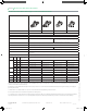
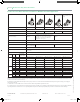
Size Cv Kvs
Rangeability
Greater Than
c
1/2”
0.4 0.3 5:1 VB-7211-0-3-01 VB-7211-0-4-01
c
VB-7221-0-4-01
c
VB-7251-0-3-01 VB-7251-0-4-01
1.3 1.1 15:1 VB-7211-0-3-02 VB-7211-0-4-02
c
VB-7221-0-4-02
c
VB-7251-0-3-02 VB-7251-0-4-02
2.2 1.9 25:1 VB-7211-0-3-03 VB-7211-0-4-03
c
VB-7221-0-4-03
c
VB-7251-0-3-03 VB-7251-0-4-03
4.4 3.8 40:1 – VB-7211-0-4-04
c
VB-7221-0-4-04
c
– VB-7251-0-4-04
5.0 4.3 40:1 VB-7211-0-3-04 – – VB-7251-0-3-04 –
3/4”
5.5 4.8 50:1 VB-7211-0-3-05 VB-7211-0-4-05
c
VB-7221-0-4-05
c
VB-7251-0-3-05 VB-7251-0-4-05
7.5 6.5 60:1 – VB-7211-0-4-06
c
VB-7221-0-4-06
c
– VB-7251-0-4-06
8.5 7.4 50:1 VB-7211-0-3-06 – – VB-7251-0-3-06 –
1”
10 8.7 60:1 – VB-7211-0-4-07
c
VB-7221-0-4-07
c
– VB-7251-0-4-07
14 12.1 60:1 VB-7211-0-3-07 VB-7211-0-4-08
c
VB-7221-0-4-08
c
VB-7251-0-3-07 VB-7251-0-4-08
16 13.8 75:1 VB-7211-0-3-08 – – VB-7251-0-3-08 –
1-1/4”
20 17.3 100:1 – VB-7211-0-4-09
c
VB-7221-0-4-09
c
– VB-7251-0-4-09
22 19 75:1 VB-7211-0-3-09 – – VB-7251-0-3-09
a. To minimize noise, ensure the flow rate in the piping is less than 10 ft (3M) / Second and the differential pressure is less than 35 psi (241 kPa), operating
with differential pressures above 35 psi may result in additional noise but is acceptable up to 87 psi (600 kPa). Operating within the cavitation zone may
result in noise and internal valve damage.
b. Maximum recommended differential pressure in open position. Do not exceed recommended differential pressure (pressure drop), as integrity of
parts may be affected.
c. The VB-7211-0-4-xx and VB-7221-0-4-xx series valves all have rangeabilities greater than 100:1
d. To minimize noise, ensure the flow rate in the piping is less than 10 Ft (3M) / second and the maximum differential pressure is less than 35 psi (241 kPa).
Operating within the cavitation zone or an operating differential pressure above 35 psi (241 kPa) may result in noise and internal valve damage.
F-27649-1.indd 4 3/28/14 1:09 PM