
User Guide


6 © Copyright 2006 TAC All Rights Reserved. F-24384-1
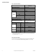
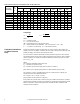
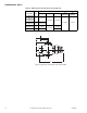
Table-6 Steam Capacity in Pounds Per Hour for VB-7221 Series.
C
v
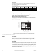
Equation
Where:
C
v
= Coefficient of flow
Q = Lbs. per hour of steam
ΔP = Differential pressure in psi (pressure drop)
P2 = Outlet pressure in psia (absolute) (P2 = Inlet pressure + 14.7 –
ΔP)
K = 1 + (0.0007 x °F superheat) (K = 1 for saturated steam)
Cavitation Limitations
on Valve Pressure
Drop
A valve selected with too high a pressure drop can cause erosion of discs and/or wire
drawing of the seat. In addition, cavitation can cause noise, damage to the valve trim (and
possibly the body), and choke the flow through the valve.
Do not exceed the maximum differential pressure (pressure drop) for the valve selected.
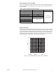
The following formula can be used on higher temperature water systems, where cavitation
could be a problem, to estimate the maximum allowable pressure drop across the valve:
Pm = 0.5 (P
1
– Pv)
Where:
Pm = Maximum allowable pressure drop (psi)
P
1
= Absolute inlet pressure (psia)
Pv = Absolute vapor pressure (psia) (refer to Table-6 or Table-7)
Note:
Add 14.7 psi to gauge supply pressure to obtain absolute pressure value.
For example, if a valve is controlling 200°F water at an inlet pressure of 18 psig, the
maximum pressure drop allowable would be:
Pm = 0.5 [(18 + 14.7) – 11.53] = 10.6 psi
(Vapor pressure of 200°F water is 11.53 psia.)
If the pressure drop for this valve is less than 10.6 psi, cavitation should not be a problem.
Systems where cavitation is shown to be a problem can sometimes be redesigned to provide
lower inlet velocities. Valves having harder seat materials should be furnished if inlet
velocities cannot be lowered.
Valve Body
Part Number
Cv
Ratin
g
Differential Pressure (
ΔP in psi)
a
a
Values are for saturated steam (K = 1). Left column under each inlet pressure is for two-position control, and right column is for proportional control.
2 psig Inlet 5 psig Inlet
10 psig
Inlet
15 psig
Inlet
20 psig
Inlet
25 psig
Inlet
30 psig
Inlet
35 psig
Inlet
0.2 1.6 0.5 4 1 8 1.5 12 2 14 2.5 16 3 18 3.5 20
VB-7221-0-4-1 0.4 2.2 5.9 3.7 9.5 5.8 14 7.8 18 9.7 20 12 23 13 26 15 29
VB-7221-0-4-2 1.3 7.1 19 12 31 19 45 25 57 32 66 38 76 44 86 50 95
VB-7221-0-4-3 2.2123220523276439653112641297414584161
VB-7221-0-4-4 4.4 24 65 41 105 64 153 86 192 107 225 127 257 148 289 168 322
VB-7221-0-4-5 5.5 30 81 51 131 80 191 107 240 133 281 159 321 185 362 210 402
VB-7221-0-4-6 7.5 41 111 70 178 110 260 146 328 182 383 217 438 252 493 286 548
VB-7221-0-4-7 10 55 147 93 238 146 347 195 437 243 511 289 584 336 658 381 731
VB-7221-0-4-8 14 76.3 206 130 333 204 485 273 612 340 715 405 818 470 921 534 1024
VB-7221-0-4-9 20 109 295 186 475 292 694 390 874 485 1021 579 1168 671 1315 763 1462
C
v
=
QK
Q=
K
ΔP • P23
ΔP • P23C
v