
User Guide


F-24381-2 © Copyright 2008 TAC All Rights Reserved. 7
INSTALLATION
Inspection Inspect the package for damage. If damaged, notify the appropriate carrier immediately.
If undamaged, open the package and inspect the device for obvious damage. Return
damaged products.
Requirements • Tools (not provided): Pipe wrenches
• Training: Installer must be a qualified, experienced technician
• Appropriate accessories
Caution:
• Install the valve with the flow in the direction of the flow arrow (“A” port is the inlet and
“AB” port is the outlet).
• Do not exceed the ratings of the device.
• Avoid locations where excessive moisture, corrosive fumes, or vibration are present.
Mounting 1. The valve should be mounted in a weather protected area in a location that is within the
ambient limits of the actuator. When selecting a location, allow sufficient room for valve
linkage, actuator, and other accessories and for service of the product.
2. The preferred mounting position for the valve is with the valve stem vertical above the
valve body. Avoid mounting the valve so that the valve stem is below horizontal.
3. On steam applications where the ambient temperature approaches the limit of the
actuator, the valve stem should be mounted 45° from vertical.
4. The VB-7212-0-4 series of flared valve bodies conform to SAE 45°. The valves must be
piped with the “A” port as the inlet and the “AB” port as the outlet.
CHECKOUT
1. Make sure the valve stem operates smoothly before installing the valve linkage and the
actuator.
2. If the stem does not operate smoothly, it may indicate that the valve was twisted or
crushed during installation or that the stem was bent by rough handling. These
conditions may require that the valve be replaced.
3. After the piping is under pressure, check the valve body and the connections for leaks.
4. After the valve linkage and the actuator are installed, check their operation.
a. Power the actuator and run the valve to the stem down position. Make sure the
linkage and valve stem stroke fully. At the stem down position, the valve should shut
off tightly.
b. For spring return actuators, allow the actuator to spring return to the stem up
position. Again, the valve stem and linkage should operate smoothly. At the stem
up position, the valve should be in its full open position.
MAINTENANCE &
FIELD REPAIR
Regular maintenance of the total system is recommended to assure sustained performance.
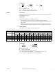
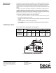
See Table-8 for maintenance kit part numbers.
Table-8 Maintenance Kits for VB-7212 Valves.
Valve Body
Part Number
Replacement
Packing Assembly
Packing Wrench Valve Repair Kit
a
VB-7212-0-4-1
YBA-622-1 TOOL-20-1
RYB-721-1
VB-7212-0-4-2 RYB-721-2
VB-7212-0-4-3 RYB-721-3
VB-7212-0-4-4 RYB-721-4
a
Kit includes replacement packing and stem & plug assembly.