
Brochure
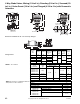


3-Way Globe Valves, Mixing (1/2 to 2 in.), Diverting (1/2 to 2 in.), and Screwed,
Union Sweat (1/2 to 2 in.) with Hydraulic Actuators
F-27414-1 © Copyright 2006 TAC. All Rights Reserved. 85
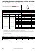
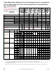
TABLE 4. Factory Assemblies, select exact Actuator Code (XXX). Any MA-52XX, MF-5X1X, MP-5XXX, MPR-5X1X can be
assembled to 1/2 to 1-1/4 in. valve bodies with the close-off pressure ratings listed in Table 2. Select below listed Hydraulic
Actuators or Actuator Codes (XXX) for factory available assemblies. For applications that factory assemblies are not available,
select actuator, linkage, valve body and field assemble.
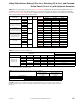
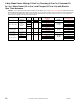
TABLE 5. Dimensions in Inches
(Millimeters).
Input Signal
Voltage
Vac 50/60 Hz
VA
Aux.
Switch
Actuator
Part No.
Actuator Code (XXX) for Factory Available Assembly
VA-73X3 VS-73X3 VF-7313
Two-Position SPST
24
18
No
MA-5213 201 ——
120 MA-5210 211 ——
240 MA-5211 221 ——
2 to 15 Vdc, TAC System
8000, stroke occurs 6 to 9
Vdc approx., non-positive
positioning
24
18
MP-5213 — 201 —
120 MP-5210 — 211 —
240 MP-5211 — 221 —
2 to 15 Vdc, TAC System
8000, start 6 Vdc factory set,
adjustable 2 to 12 Vdc, 3 Vdc
span, positive positioning
24
18
MP-5413 —
247
a
a
includes AV-601.
—
120 MP-5410 —
244
a
—
240 MP-5411 —
245
a
—
0 to 10 Vdc, System 800,
Start 0.5 Vdc Factory Set,
Positive Positioning
24
MP-5513
257
a
120 MP-5510
254
a
240 MP-5511
255
a
4 to 20 mA
24
18
MPR-5613 —
267
a
—
120 MPR-5610 —
264
a
—
240 MPR-5611 —
265
a
—
Floating SPDT 24 21
MF-5413 ——
221
a
MF-5513 ——
223
a
Valve Body
Actuator Series
MA/MF/MP/MPR-5XXX
a
a
Add 2-3/32 in. (53 mm) to the “E” dimension for a valve assembly using an AV-601 linkage extension.
Part Number
Size (in.) A
B
b
b
Use B and D dimensions for VB-7314 valve body.
C
D
b
E
VB-7313-0-4-P
VB-7314-0-4-P
VB-7323-0-4-P
1/2 3 (76) 4-3/16 (106) 1-3/8 (35) 2-5/16 (59) 7-7/8 (200)
3/4 3-5/8 (92) 5-7/16 (138) 1-11/16(43) 2-5/8 (67) 7-7/8 (200)
1
4-5/8 (117)
6-5/8 (168) 1-9/16 (40) 3-1/8 (79) 7-15/16 (202)
1-1/4 6-13/16 (173) 1-5/8 (41) 3-7/16 (86) 8-3/16 (208)
1-1/2 5-3/8 (137) 8-5/16 (211) 1-9/16 (40) 3-3/4 (121) 8-5/16 (211)
2 6-1/8 (156) 9-3/16 (233) 1-7/8 (48) 4-3/16 (106) 8-3/8 (213)
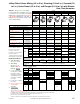
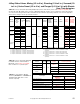
TABLE 6. Ambient Temperature Restrictions for Valve Actuators.
a
a
Actuator condensation can be prevented by use of the “Linkage Extension.”
CAUTION: Condensation can facilitate condensation. Piping insulation must not cover any part of the actuator or
mounting nut. With 40°F (4°C) water, the maximum allowable dew point temperature without a linkage extension is
68°F (20°C).
Temperatures °F (°C)
MF-5X13, MPR-561X,
MP-521X-XXX w/AV-601
Linkage Extension
MF-5X13, MPR-561X,
MP-5X1X-XXX w/AV-601
Linkage Extension
Maximum Ambient 140 (60) 140 (60)
Maximum Allowable Fluid 281 (138) 140 (60)
VB-73XX--0-4-P Maximum Fluid 281 (138) 281 (138)
Max. Allw.Ambient 140 (46) 103 (39)