
Brochure
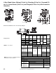


3-Way Globe Valves, Mixing (1/2 to 6 in.), Diverting (1/2 to 6 in.), Screwed (1/2
to 3 in.), Union Sweat (1/2 to 2 in.) and Flanged (2-1/2 to 6 in.) with Pneumatic
Actuators
82
© Copyright 2006 TAC. All Rights Reserved. F-27414-1
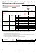
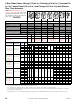
American Standard 125 lb. Cast Iron Pipe Flanges.
Flange Detail.
Nominal
Pipe
Size
Flanges Drilling Bolting
Length of
Machine
Bolts
F
Flange
Diameter
A
Flange
Thickness
B
Diameter of
Bolt Circle
D
Diameter of
Bolt Holes
E
Number
of
Bolts
Diameter
of
Bolts
2-1/2
7 11/16 5-1/2
3/4
4
5/8
2-1/2
3
7-1/2 3/4 6
4 9
15/16
7-1/2
8
3
5 10 8-1/2
7/8 3/4
6 11 1 9-1/2 3-1/4
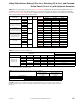
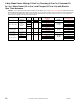
TABLE 5. Flow Pattern.
Body
Part Number
Flow
Type
Stem Up (SU)
(Normal Position)
Stem Down (SD)
Flow Closed Port Flow Closed Port
VB-7313-0-4-P
VB-7314-0-4-P
VB-9313-0-4-P
Mixing
B to AB A
A to AB B
VB-7323-0-4-P
VB-9323-0-4-P
Diverting B to A AB
VB-9313-0-5-P Mixing A to AB B
VB-9323-0-5-P Diverting C to L U C to U L
TABLE 6. Restrictions on Maximum Ambient
Temperature for Valve Actuators.
TEMPERATURES °F (°C)
Actuators
All
Maximum Ambient
220 (104)
Max. Allowable Fluid
250 (121)
VB-9313-0-5-P
VB-9323-0-5-P
Maximum Fluid
300 (149)
Max. Allowable Ambient
100 (38)
VB-7313-0-4-P
VB-7314-0-4-P
VB-7323-0-4-P
VB-9313-0-4-P
VB-9323-0-4-P
Maximum Fluid
281 (138)
Max. Allowable Ambient
160 (71)
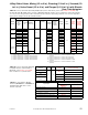
16-5/8
(2-1/2–4")
19
(5-6")
C
B
See Flange
Detail Table
A
A
A
B
E
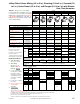
3
12-1/2
10-5/16
MK-8XX1 with
VB-9313-0-5-P
10-5/16
A
12-1/2
3
E
C
UL
C
See Flange
Detail Table
MK-68X1 or
MK-6911 with
VB-9323-0-5-P
16-5/8
(1-1/2 - 3")
E
3
12-1/2
10-5/16
C
MK-8XX1 with VB-7313-0-4-P
A
D
A
E
B
F
Length of Machine Bolt