
Brochure


3-Way Globe Valves, Mixing (1/2 to 6 in.), Diverting (1/2 to 6 in.), Screwed (1/2
to 3 in.), Union Sweat (1/2 to 2 in.) and Flanged (2-1/2 to 6 in.) with Pneumatic
Actuators
F-27414-1 © Copyright 2006 TAC. All Rights Reserved. 79
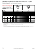
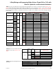
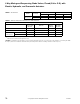
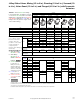
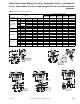
TABLE 2A. 1/2 to 4 in. Valves,
select Actuator or Actuator Code
(XXX) having sufficient close-off for
the application. If selecting
Component Parts, select
and Positive
Positioner if required. (Also refer to
Table 2B).
Effective Area (stroke) 50 Sq. In. (1/2 In.) 50 Sq. In. (1 In.)
50 Sq. In. (1-1/2
in.)
Valve Linkage VB-7313-0-4-P AV-430 — —
Valve Linkage VB-9313-0-5-P &
VB-9313-0-4-12 & 13
— AV-495
—
Valve Linkage VB-7323-0-X-P &
VB-9323-0-X-P
AV-430 AV-430 AV-430
Positive Positioner AK-42309-500 AK-42309-500 AK-42309-500
Factory Assembly with Positive Positioner No Yes Yes No Yes Yes Yes
Actuator Code (XXX) 611 612 613 601 602 603 653
Actuator MK-6601 MK-6611 MK-6621 MK-6801 MK-6811 MK-6821 MK-6921
Spring Range (psig) 3 to 8 5 to 10 8 to 13 3 to 8 5 to 10 8 to 13 8 to 13
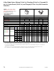
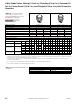
ACTUATOR CLOSE-OFF PRESSURE RATING (psi)
abce
a
Close-off ratings for mixing or sequencing valves: (SU = “A”, SD = “B” port). “A” port (SU) ratings equal pressure at port “A” minus pressure at port “B”. “B” port (SD) ratings equal
pressure at port “B” minus pressure at port “A”. Close-off ratings in the table are true only when the indicated supply air pressure is applied to the actuator. A change in air pressure
at the actuator alters the actual close-off pressure.
b
Close-off pressure ratings describe only the differential pressure which the actuator can close-off to standards with adequate seating force. Consult valve body specifications for
other limitations.
c
Mixing valve are not to be used in diverting applications. Diverting valves may be used in mixing applications with minor affects on flow.
Supply Air Pressure (psig)
15/20 15 20 15/20 15 20 15/20 15 20 15/20 15 20 15/20 15 20 15/20 15 20 20 20
Stem Position
d
d
SU ⎯ Stem Up; SD ⎯ Stem Down. Refer to Table 5 for flow pattern, port designations and normal position.
SU SD SD SU SD SD SU SD SD SU SD SD SU SD SD SU SD SD SU SD
Valve Assembly Valve Body P Code
Size
in.
——— ——— ———————————— — —
VK-7313-XXX-4-P
VK4-7313-XXX-4-P
VB-7313-0-4-P
VB-7314-0-4-P
-10 1-1/2 40 170 250 80 110 230 170 30 160
— ———————— — —
-11 2 20 90 160 50 60 120 90 15 90
— ———————— — —
VK-9313-XXX-4-P
VK4-9314-XXX-4-P
VB-9313-0-4-P
-12 2-1/2
——— ——— ———
10 60 110 30 40 91 60 9 60
——
-13 3
——— ——— ———
5 417520276240 540
——
VK-9313-XXX-5-P
VK4-9313-XXX-5-P
VB-9313-0-5-P
-12 2-1/2
——— ——— ———
10 60 110 30 40 91 60 9 60
——
-13 3
——— ——— ———
5 407520276240 540
——
-14 4
——— ——— ———
22 40 10 14 33 20
—
22
——
VK-7323-XXX-4-P
VK4-7323-XXX-4-P
VB-7323-0-4-P
-10 1-1/2
250 250 250 250 250 250 250 250 250
— ———————— — —
-11 2
— ———————— — —
VK-9323-XXX-5-P
VK4-9323-XXX-5-P
VB-9323-0-5-P
e
e
Leakage ratings on 2 1/2 to 6 inch VB-9323 diverting valves are ANSI II (0.5%). Maximum differential pressure between opposite end ports is 50 psi.
-12 2-1/2
——— ——— ——————
100 100 100 100
—
100
——
-13 3
——— ——— —————— — — —
-14 4
——— ——— ————————————
125 125-15 5
——— ——— ————————————
-16 6
——— ——— ————————————
Valve Linkage