
Brochure


2-Way Globe Valves, Screwed (1/2 to 3 in.), Union Sweat (1/2 to 2 in.) and
Flanged (2-1/2 to 6 in.) with Electric Gear Train Actuators
F-27414-1 © Copyright 2006 TAC. All Rights Reserved. 41
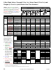
American Standard 125 lb. Cast Iron Pipe Flanges.
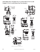
Flange Detail
Dimensions in Inches (Metric Conversion 25.4 mm = 1 in.).
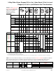
TABLE 6. Restrictions on Max. Ambient Temperature for Valve Actuators.
Nominal
Pipe Size
Flanges Drilling Bolting
Flange
Diameter
A
Flange
Thickness
B
Diameter of
Bolt Circle
D
Diameter of
Bolt Holes
E
Number of
Bolts
Diameter of
Bolts
Length of
Machine Bolts
F
2-1/2
7 11/16 5-1/2 3/4 4 5/8 2-1/2
3
7-1/2 3/4 6 3/4 4 5/8 2-1/2
4
9 15/16 7-1/2 3/4 8 5/8 3
5 10 15/16 8-1/2 7/8 8 3/4 3
6 11 1 9-1/2 7/8 8 3/4 3-1/4
Temperatures °F (°C)
Actuator Code (XXX)
3XX, 40X, 41X,
42X, 44X
46X 90X 25X 256 301 303
365
366
MF-22XX3
a
a
MF-22203 for hot water and steam applications only.
MS-22353 MF-63103 MF-63123 MS-79X3
Maximum Ambient °F (°C)
136 (57) 136 (57) 130 (54) 140 (60) 140 (60) 140 (60) 122 (50)
Max. Allowable Fluid
260 (126) 260 (126) 260 (126) 220 (104) 220 (104) 260 (126) 260 (126)
VB-7213-0-4-P
VB-7214-0-4-P
VB-9213-0-4-P
VB-9213-0-5-P
Max. Fluid
281 (138) 281 (138) 281 (138) 281 (138) 281 (138) 281 (138) 281 (138)
Max. Allow.
Ambient °F (°C)
125 (52) 125 (52) 125 (52) 115 (46) 115 (46) 125 (52) 115 (46)
VB-7273-0-4-P
Max. Fluid
366 (183)
——
281 (138) 340 (171) 340 (171)
Max. Allow.
Ambient °F (°C)
100 (38) 115 (46) 100 (38) 100 (38)
VB-7253-0-4-P
Max. Fluid
340 (171) 281 (138) 366 (185) 366 (171)
Max. Allow.
Ambient °F (°C)
100 (38) 115 (46) 100 (38) 100 (38)
D
Length of Machine Bolt
A
E
B
F
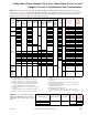
Valve Assemblies Valve Body Action Factory Shipped Position Action
Valve Stem Flow
VX-721X-XXX-4-P
VX-722X-XXX-4-P
VX-731X-XXX-4-P
VX-732X-XXX-4-P
2-Way Stem Up Open
2-Way Stem Up Closed
3-Way Mixing
3-Way Diverting
Up
Up
Up
Up
Open
Closed
Flow B to AB
Flow B to AB
A to AB Flow decreases as actuator rotates CW
A to AB Flow increases as actuator rotates CW
A to AB Flow increases as actuator rotates CW
B to AB Flow decreases as actuator rotates CW
B to A Flow increases as actuator rotates CW
B to AB Flow decreases as actuator rotates CW
The configuration of the valve assembly determines the valve stem position and
flow, as shipped from the factory. See the table below.