
Brochure
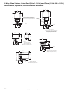

2-Way Globe Valves, Union End (1/2 to 1-1/4 in.) and Flared (1/2 & 5/8 in. O.D.)
with Electric, Hydraulic, and Pneumatic Actuators
14
© Copyright 2006 TAC. All Rights Reserved. F-27414-1
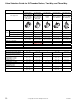
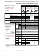
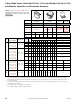
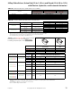
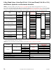
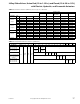
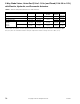
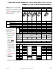
TABLE 2. Select Actuator Type with correct
Input Signal having sufficient close-off for the
application. If selecting Component parts, Select
Input Signal
Pneumatic Pneumatic
Two-Position
Electric
Electronic Vdc
4 to 20 mA
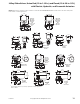
Valve Linkage
AV-7400 AV-401
AV-7600
a
a
MF-5X1X, MP-541X, MP-551X MPR-561X, use AV-7600-1 and AV-601.
Positive
Positioner
AK-42309-500 AK-42039-500 — —
Actuator Type
MK-2690 MK-4601 MK-4611 MK-4621
MA-521X-XXX
MF-5X1X
MP-521X-XXX
MP-541X
MP-551X
MPR-561X
Actuator Code
201 202 203 301 302 303 2XX
Spring Range
(psig)
3 to 7 5 to 10 8 to 13 3 to 6 5 to 10 10 to 13 —
ACTUATOR CLOSE-OFF PRESSURE RATING (psi)
b
c
b
Close-off rated for ANSI IV (.01%) with pressure at inlet (port A). Ratings for normally open valves are with indicated supply air pressure applied to
actuator. Ratings for normally closed valves are with 1 psi or less applied to actuator (for kPa multiply by 6.89). See “Valve General Information” section
for seat leakage ratings.
c
Close-off pressure ratings describe only the differential pressure which the actuator can close-off with adequate seating force. Consult valve body
specifications for other limitations.
N.P.
Factory Available
Valve Assemblies
d
d
Consult price guide for factory available valve assemblies.
Valve Body P Code
Size
in.
Supply Air Pressure (psig) —
15 20 15 20 15 20 15 20 15 20 15 20 —
N.O.
VA-7211-XXX-3-P
VF-7211-2XX-3-P
VK-7211-XXX-3-P
VS-7211-XXX-3-P
VB-7211-0-3-P
-1-2-3-4 1/2 130 220 60 170 — 90 250 250 — — 10 200 130
-5-6
3/4
80 130 40 120 — 60 180 250 — — — 120 80
-7-8 1 35 70 — 50 — 25 90 150 — — — 65 40
-9 1-1/4 20 40 — 30 — 15 50 90 — — — 40 25
VA-7211-XXX-4-P
VA-7212-XXX-4-P
VF-7211-2XX-4-P
VF-7212-2X
X-4-P
VK-7211-XXX-4-P
VK-7212-XXX-4-P
VS-7211-XXX-4-P
VS-7212-XXX-4-P
VB-7211-0-4-P
VB-7212-0-4-P
-1-2-3-4
1/2
[5/8]
e
e
5/8 O.D. SAE 45° fittings on VB-7212 and VB-7222 valves.
130 220 60 170 — 90 250 250 120 250 10 200 130
-5-6
3/4
80 130 40 120 — 60 180 250 80 180 — 120 80
-7-8
1
35 70 15 50 — 25 90 150 35 100 — 65 40
-9
1-1/4
20 40 8 30 — 15 50 90 20 60 — 40 25
N.C.
VA-7221-XXX-4-P
VF-7221-2XX-4-P
VF-7222-2XX-4-P
VK-7221-XXX-4-P
VK-7222-XXX-4-P
VS-7221-XXX-4-P
VS-7222-XXX-4-P
VB-7221-0-4-P
VB-7222-0-
4-P
-1-2-3-4
1/
2
[5/8]
e
— — 50 130 30 100 250 200 130
-5-6 3/4 — — 30 60 20 70 160 130 80
-7-8 1 — — 9 30 5 30 60 50 40
-9
1-1/4
— — — 15 — 15 40 35 25
N.O.
VA-1219-XXX-4-P
VF-1219-XXX-4-P
VK-1219-XXX-4-P
VS-1219-XXX-4-P
VB-121-0-4-P -1, -2, -3 1/2 190 250 90 220 — 160 250 250 180 250 40 250 125
Valve Linkage