
Brochure


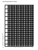
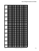


Valve Sizing Information for Water
172
© Copyright 2006 TAC. All Rights Reserved. F-27414-1
GENERAL INFORMATION REQUIRED
1. Fluid controlled:
• Chilled water, hot water, or steam.
2. Temperature limitations:
• Fluid, maximum, and minimum.
• Ambient for actuator.
3. Pressure:
• Static.
•Close-off ⎯ Fully closed.
• Differential ⎯ Pressure drop across the valve in the
fully open position.
4. End fitting:
• Union end.
• Globe screwed.
•Flared.
• Flanged.
• Flangeless.
5. For return to a known position (i.e., normally open or
normally closed): Specify 200 or 300 Series spring return
actuator.
6. Dimensional data.
7. C
v
(flow coefficient) requirement is calculated from flow
rate and differential pressure. Refer to formulas and
tables.
For additional sizing and selection background information,
refer to:
• CA-28 Control Valve Sizing, F-13755.
• CA-27 Three-Way Valves, F-12348.
• CA-15 Control of High Temperature Water Systems,
F-7638.
• CA-13 Fundamentals of Hot Water Pump Installation,
F-7767.
RECOMMENDED PRESSURE DROPS FOR WATER
Refer to specific valve data in this catalog for maximum
allowable pressure drops and close-off ratings.
A. Two-Position Valves
Two-position valves are normally selected “line size” to keep
pressure drop at a minimum. If desirable to reduce valve
below line size, then 10% of “available pressure” normally
used to select valve.
B. Proportional Two-Way Valves
Usually selected to take a pressure drop equal to at least
50% of the “available pressure” (i.e., the pump pressure
differential available between supply and return mains with
design flow at the valve location). As “available pressure” is
often difficult to calculate, the normal procedure is to select
the valve using a pressure drop at least equal to the drop in
the coil or other load being controlled (except where small
booster pumps are used), but never less than 5 psi (34 kPa).
When design temperature drop is less than 60°F (33°C) for
conventional systems, higher pressure drops across the
valve are needed for good control results. Refer to the
following table.
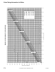
The calculated C
v
usually falls between two valve sizes. If the
pressure drop of the smaller is acceptable for the application,
select the smaller valve for better control.
C. Proportional Three-Way Valves
Recommended Pressure Drop ⎯ Bypass Application: 50% of
“available pressure”, or equal to pressure drop through the
load at full flow.
Three-way valves in the return used to control output by
throttling water flow to the load (bypass applications) are
controlling output in the same manner as throttling two-way
valves, and must be selected using the same high pressure
drops if good control results are to be obtained.
Recommended Pressure Drop ⎯ Constant Flow
Applications: 20% of “available pressure”, or equal to 1/4 of
the pressure drop through the load at full flow.
Three-way valves used with individual pumps to control
output by varying water temperature to the load (constant
flow applications) are controlling output by mixing two water
sources at different temperatures, and do not require high
pressure drops for good control results.
CAVITATION LIMITATIONS ON VALVE PRESSURE
DROP
A valve selected with too high a pressure drop can cause
erosion of discs and/or wire drawing of the seat. In addition,
cavitation can cause noise, damage to the valve trim (and
possibly the body) and choke the flow through the valve.
Do not exceed the maximum differential pressure (pressure
drop) for the valve selected.
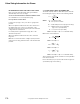
The following formula can be used on higher temperature
water systems, where cavitation could be a problem, to
estimate the maximum allowable pressure drop across the
valve:
Pm = 0.5 (P
1
- Pv)
Pm = Maximum allowable pressure drop
P
1
= Absolute inlet pressure (psia)
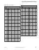
Pv = Absolute vapor pressure (refer to Vapor
Pressure of Water Table or Steam Table)
Note: Add 14.7 psi to gauge supply pressure to obtain
absolute pressure value.
Valve
Sizing
Informa
tion for
Water
Conventional Heating Systems
Coil Temp. Drop °F
(°C)
Recom. Valve Pressure Drop
a
(% of Available Pressure)
Valve Pressure
Drop
60 (33) or more 50% 1 x load drop
40 (22) 66% 2 x load drop
20 (11) 75% 3 x load drop
a
Recommended minimum pressure drop ⎯ 5 psi (34 kPa).
Secondary Circuits with Small Booster Pumps
50% of Available Pressure Difference (Equal to drop
through load, or 50% of booster pump head)