
Brochure


3-Way Mixing and Diverting Butterfly Valves, Flangeless (2 to 24 in.) with
Electric Gear Train and Pneumatic Actuators
F-27414-1 © Copyright 2006 TAC. All Rights Reserved. 111
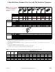
tee numbers
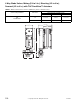
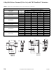
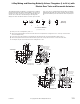
The 3-Way Assemblies are shipped as a complete unit, assembled,
mounted and tested, fully ready for field installation. Two valves are
mounted on a 125 lb. cast iron tee; one valve complete with power
actuator, the second valve controlled through connecting slave
linkage. The valves are linked so that as one valve opens, the other
valve closes. The tee arrangement desired should be specified by
indicating the appropriate tee position (1 through 7 below), and the
placement of both the power valve and slave valve respectively as
on:
125 lb. Flanged
Cast Iron Tee
4 Alignment Holes
Match 125-150 lb.
Flange Drilling
Slave Valve
Power Valve
E
E
E
16-1/4
A
9-/12
3
30
6
6-3/4
2
B
D
Outboard
Bearings
Adjustable
Packing Nut
FC
VC-6664 (2"–12")
VP-6664 (2"–12")
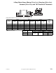
125 lb. Flanged
Cast Iron Tee
4 Alignment Holes
Match 125-150 lb.
Flange Drilling
Slave Valve
Power Valve
E
E
A
E
3
30
6
2
F CB
D
3
Outboard
Bearings
20-3/8
6-3/4
9-1/2
Adjustable
Packing Nut
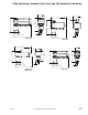
VC-6665 (8" - 24")
VP-6665 (8"–24")
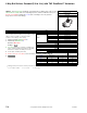
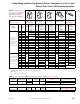
1.) Each port on Tee is designated by A, B, or C.
2.) All Tee arrangement numbers are based on Plan View of the Tee (Elevation: Looking down on Tee and Top of valve shaft as
shown in example below).
3.) Power valve (valve with actuator) is designated by the first letter after the Tee Selection Number. Either A, B, or C.
4.) All Tee arrangements are based on the bracket for the power valve to be positioned at 12:00 O'clock in the Plan View.
As an example, the plan view shown below are tee arrangements: 1 B C.
AB
C
AB
C
A
B
C
A
B
C
ABC
A
B
C
Plan View
(Elevation)
1235
6
7
Tee Selection Numbers
(1, 2, 3, 4, 5, 6, 7)