
Brochure
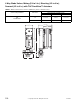
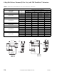
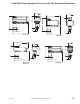

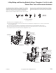

3-Way Ball Valves, Screwed (1/2 to 2 in.) with TAC DuraDrive™ Actuators
F-27414-1 © Copyright 2006 TAC. All Rights Reserved. 105
TABLE 2. Select Actuator Type or
Actuator Code (XXX) series with
correct Input Signal having
sufficient close-off for the
application.
Non-Spring Return Spring Return
Input Signal Floating and Proportional SPDT, Floating and Proportional SPDT
Ball Valve with Linkage Assembly VB-2353-505-8-XX VB-2353-506-8-XX VB-2353-510-8-XX VB-2353-506-8-XX VB-2353-550-8-XX — VB-2353-510-8-XX —
Normal Position N.C. N.O.
Valve Assembly Type VF or VS VA, VF or VS VA
Actuator Code (XXX) 505 506 508 512, 514, 516
532. 533. 534. 535.
536. 537
542, 543, 544, 545,
546, 547
552, 553,
554, 555,
556, 557
562, 563,
564, 565,
566, 567
572, 574, 576 582, 584, 586
Actuator Types
MF40-6043
MS40-6043
MF40-6083
MS40-6083
MF40-6153
MS40-6153
MF40-6343
MS40-634X
MA40-704X
MF40-7043
MS40-7043
MA40-707X
MF40-7073
MS40-7073
MA40-715X
MF40-7153
MS40-7153
MA40-717X
MF40-7173
MS40-717x
MA40-717X
Factory Available
Valve Assemblies
a
a
Consult price guide for factory available valve assemblies.
P Code
Size
in.
Cv
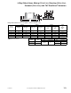
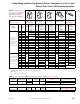
VALID VALVE/ACTUATOR COMBINATIONS
bc
b
Non-spring return two-way ball valve assemblies are shipped normally closed, voltage rise to open.
c
Seat leakage rating of ANSI class IV (.01%).
VX-2353-XXX-8-P
21 1/2
5.4
X
d
d
Do not use these ball valve assemblies when the frequency of operation is les than once every 30 days. It is recommended that the next larger size ac-
tuator is selected.
XX — X X X— X —
41 3/4
12.0 —
X
d
X
d
—X XX — X—
51
1
14.0 — — X X — — X — X —
61
1-1/4
21.0 — — — X — — — X
X
d
X
71 1-1/2
34.0 — — — X — — — X — X
81
2
47.0 — — —
X
d
———
X
d
—
X
d
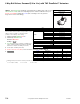
Valve Assembly
Part Number
P Code
Size
in.
Cv
k
vs
e
e
k
vs
= m
3
/h (ΔP = 100 kPa)k
vs
= C
v
/ 1.158C
v
= k
vs
x 1.156
Ball Valve & Linkage Only (-XXX-)
f
f
Part number subcode (-XXX-) listed matching valid actuator/valve combinations in above table.
VX-2353-XXX-8-P
g
g
To determine a specific part number, see the Ball Valve Assembly Part Numbering System,.
21
1/2 5.4 4.7 505 506 506 — 530 550 550 — 510 —
41
3/4 12.0 10.4 — 506 506 — 506 550 550 — 510 —
51
1 14.0 12.1 — — 506 510 — — 550 — 510 —
61
1-1/4 21.0 18.2 — — — 510 — — — — 510 —
71
1-1/2 34.0 29.4 — — — 510 — — — — — —
81
2 47.0 40.6 — — — 510 — — — — — —
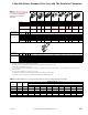
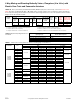
TABLE 3. Estimated Effective C
v
when Using Pipe Reducers with Three-Way Ball Valve Assemblies.
Valve Size
(in.)
P Code C
v
Estimated Effective C
v
(k
vs
)
Pipe Size
- inches (NPT)
1/2 3/4 1 1
-1/4 1-1/2 2 2-1/2 3 4
1/2 21 5.45.4 (4.7)4.8 (4.2)4.5 (3.9)——————
3/4 41 12.0—12.0 (10.4)11.2 (9.7)10.5 (9.1)10.0 (8.6)————
1 51 14.0 — — 14.0 (12.1) 13.7 (11.8) 13.3 (11.5) 12.9 (11.2) — — —
1
-1/4 61 21.0 — — — 21.0 (18.2) 20.7 (17.9) 19.9 (17.2) 19.4 (16.8) — —
1
-1/2 71 34.0————34.0 (29.4)32.8 (28.4)31.6 (27.3)30.8 (26.6)—
2 81 47.0—————47.0 (40.6)46.3 (40.0)45.4 (39.3)44.2 (38.2)