
User Guide
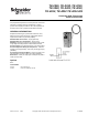
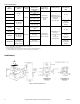
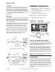
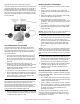
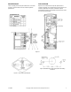
Table Of Contents
- GENERAL INFORMATION
- Options
- Table-1 Model Chart.
- Figure-1 Mounting Dimensions.
- INSTALLATION
- Locating
- Mounting
- One Temperature Thermostats
- 1. The scale on the thermostat represents 30°F (17°C) or 60°F (33°C) span (see page 1) with the desired control point in the center. Each division is equal to 5°F (3°C) for 30°F (17°C) span units and 10°F (6°C) for 60°F (33°C) span units.
- 2. Observe the temperature of the bulb using a test thermometer. Turn the knob of the thermostat to the point on the scale which would correspond to the bulb temperature. Read the branch line pressure. It should be 8 psig ±1 psig (55 kPa ±7 kPa).
- 3. If the pressure is not 8 psig (55 kPa) use a .048" Bristol wrench (TOOL-82) in the calibrating screw and adjust the screw to ...
- 4. When the calibration has been completed, turn the knob to the desired setpoint and remove the gauge, reconnect the branch line and replace the cover.
- 1. The scale on the thermostat represents 30°F (17°C) or 60°F (33°C) span (see page 1) with the desired control point in the center. Each division is equal to 5°F (3°C) for 30°F (17°C) span units and 10°F (6°C) for 60°F (33°C) span units.
- Heating-Cooling Thermostats
- 1. Adjust the supply line pressure for the system to 25 psig (172 kPa).
- 2. Connect a pressure regulator into the supply main between the main and the thermostat at the thermostat location.
- 3. Adjust the regulator to 20 psig (138 kPa); at this supply pressure the thermostat is direct acting.
- 4. Set the dial knob on the thermostat to the bulb temperature setting and observe the branch line control air pressure. This pressure should be 8 psig ±1 psi (55 kPa ±7 kPa).
- 5. If not, adjust the direct acting screw to obtain 8 psig (55 kPa) branch line control pressure using a .048" Bristol wrench (Tool-82).
- 6. Adjust the regulator in the main line to 15 psig (103 kPa). At this supply pressure the temperature is reverse acting.
- 7. Observe the branch line control air pressure. If this pressure is not 8 psig (55 kPa), use a .048" Bristol wrench (TOOL-82) and adjust the reverse acting calibrating screw to obtain an 8 psig (55 kPa) branch line control pressure.
- 8. Recheck calibration by switching the supply pressure between 15 and 20 psig (103 and 138 kPa) several times and observe the control pressure. If it varies from the desired pressure, repeat the calibration procedures.
- 9. Calibration is now complete. Turn the adjusting knob to the desired setpoint. Remove the test gauge and regulator, reconnect the main and branch lines and replace the cover.
- 1. Adjust the supply line pressure for the system to 25 psig (172 kPa).
- Heating-Cooling Low Limit TK-4212-201
- Figure-6

F-12585-8 © Copyright 2009 Schneider Electric All Rights Reserved. 5
MAINTENANCE
This is a quality product. Regular maintenance of the total
system is recommended to assure sustained optimum
performance.
FIELD REPAIR
Repair is not recommended except for replacement of
restrictor assembly. Use AT-529 restrictor kit (see Figure 6) if
restrictor replacement is required. Otherwise, replace
thermostats if system is not operating correctly and the cause
is traced to the thermostat.
Figure-6
Figure-7 AT-208 Duct Mounting Kit.
Figure-8 Bulb Mounting Hole Arrangement for Drilling
Ductwork.