
User Guide
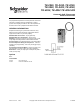
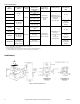
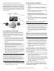
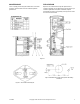
Table Of Contents
- GENERAL INFORMATION
- Options
- Table-1 Model Chart.
- Figure-1 Mounting Dimensions.
- INSTALLATION
- Locating
- Mounting
- One Temperature Thermostats
- 1. The scale on the thermostat represents 30°F (17°C) or 60°F (33°C) span (see page 1) with the desired control point in the center. Each division is equal to 5°F (3°C) for 30°F (17°C) span units and 10°F (6°C) for 60°F (33°C) span units.
- 2. Observe the temperature of the bulb using a test thermometer. Turn the knob of the thermostat to the point on the scale which would correspond to the bulb temperature. Read the branch line pressure. It should be 8 psig ±1 psig (55 kPa ±7 kPa).
- 3. If the pressure is not 8 psig (55 kPa) use a .048" Bristol wrench (TOOL-82) in the calibrating screw and adjust the screw to ...
- 4. When the calibration has been completed, turn the knob to the desired setpoint and remove the gauge, reconnect the branch line and replace the cover.
- 1. The scale on the thermostat represents 30°F (17°C) or 60°F (33°C) span (see page 1) with the desired control point in the center. Each division is equal to 5°F (3°C) for 30°F (17°C) span units and 10°F (6°C) for 60°F (33°C) span units.
- Heating-Cooling Thermostats
- 1. Adjust the supply line pressure for the system to 25 psig (172 kPa).
- 2. Connect a pressure regulator into the supply main between the main and the thermostat at the thermostat location.
- 3. Adjust the regulator to 20 psig (138 kPa); at this supply pressure the thermostat is direct acting.
- 4. Set the dial knob on the thermostat to the bulb temperature setting and observe the branch line control air pressure. This pressure should be 8 psig ±1 psi (55 kPa ±7 kPa).
- 5. If not, adjust the direct acting screw to obtain 8 psig (55 kPa) branch line control pressure using a .048" Bristol wrench (Tool-82).
- 6. Adjust the regulator in the main line to 15 psig (103 kPa). At this supply pressure the temperature is reverse acting.
- 7. Observe the branch line control air pressure. If this pressure is not 8 psig (55 kPa), use a .048" Bristol wrench (TOOL-82) and adjust the reverse acting calibrating screw to obtain an 8 psig (55 kPa) branch line control pressure.
- 8. Recheck calibration by switching the supply pressure between 15 and 20 psig (103 and 138 kPa) several times and observe the control pressure. If it varies from the desired pressure, repeat the calibration procedures.
- 9. Calibration is now complete. Turn the adjusting knob to the desired setpoint. Remove the test gauge and regulator, reconnect the main and branch lines and replace the cover.
- 1. Adjust the supply line pressure for the system to 25 psig (172 kPa).
- Heating-Cooling Low Limit TK-4212-201
- Figure-6

4 © Copyright 2009 Schneider Electric All Rights Reserved. F-12585-8
Calibrate the thermostat as follows (See Figure 5):
Disconnect the branch line at the thermostat and attach a test
gauge to the fitting (B). Push the tubing on as far as it will go,
approximately 1/4" (6 mm). The tubing for this test gauge
should be approximately 6" (150 mm) long to permit bringing
the gauge out from the test point to a place where it can be
easily read. The supply pressure to the thermostat should be
15 psig (103 kPa).
Figure-5
One Temperature Thermostats
These thermostats are factory adjusted to operate at the
midpoint of the dial span, when the adjusting dial is in its
mid-position. Whenever the throttling range is changed, the
thermostat calibration should be checked and adjusted if
necessary as follows:
1. The scale on the thermostat represents 30°F (17°C) or
60°F (33°C) span (see page 1) with the desired control
point in the center. Each division is equal to 5°F (3°C) for
30°F (17°C) span units and 10°F (6°C) for 60°F (33°C)
span units.
2. Observe the temperature of the bulb using a test
thermometer. Turn the knob of the thermostat to the point
on the scale which would correspond to the bulb
temperature. Read the branch line pressure. It should be
8 psig ±1 psig (55 kPa ±7 kPa).
3. If the pressure is not 8 psig (55 kPa) use a .048" Bristol
wrench (TOOL-82) in the calibrating screw and adjust the
screw to obtain 8 psig (55 kPa). The proper screw holes
for the reverse acting or direct acting calibration are
labeled on the main lever (Figure 5).
Caution: Cae should be taken when adjusting the reverse
acting setpoint screw. Avoid unnecessary side motions and
particularly avoid lifting the lever to which the screw is
attached. Burrs on the Bristol wrench could cause it to stick in
the screw. Note also, that the hex nuts on the adjusting
screws are used to provide tension only and should not be
loosened when making calibration adjustments.
4. When the calibration has been completed, turn the knob
to the desired setpoint and remove the gauge, reconnect
the branch line and replace the cover.
Heating-Cooling Thermostats
1. Adjust the supply line pressure for the system to 25 psig
(172 kPa).
2. Connect a pressure regulator into the supply main
between the main and the thermostat at the thermostat
location.
3. Adjust the regulator to 20 psig (138 kPa); at this supply
pressure the thermostat is direct acting.
4. Set the dial knob on the thermostat to the bulb
temperature setting and observe the branch line control
air pressure. This pressure should be 8 psig ±1 psi (55
kPa ±7 kPa).
5. If not, adjust the direct acting screw to obtain 8 psig (55
kPa) branch line control pressure using a .048" Bristol
wrench (Tool-82).
Caution: Do not loosen the hex nut on the screw.This nut is
for friction purposes only; it does not lock the screw.
6. Adjust the regulator in the main line to 15 psig (103 kPa).
At this supply pressure the temperature is reverse acting.
7. Observe the branch line control air pressure. If this
pressure is not 8 psig (55 kPa), use a .048" Bristol wrench
(TOOL-82) and adjust the reverse acting calibrating
screw to obtain an 8 psig (55 kPa) branch line control
pressure.
Caution: The lever to which this screw is attached contains
a spring hinge and is pivoted on the switch point adjusting
spring. Undue side motion or forces tending to lift the switch
lever off the main lever can damage the hinge or unseal the
lever.
8. Recheck calibration by switching the supply pressure
between 15 and 20 psig (103 and 138 kPa) several times
and observe the control pressure. If it varies from the
desired pressure, repeat the calibration procedures.
9. Calibration is now complete. Turn the adjusting knob to
the desired setpoint. Remove the test gauge and
regulator, reconnect the main and branch lines and
replace the cover.
Heating-Cooling Low Limit TK-4212-201
A special Heating-Cooling Thermostat is available for unitary
heating-cooling applications. This thermostat is very similar to
the TK-4212 except:
1. The restriction plate has been removed making the unit a
one pipe thermostat. The air signal to the main connection
actuates only the switchover parts.
2. The R.A. calibration screw has been removed. Therefore,
when the main pressure is reduced to 15 psig (103 kPa).
there is no calibration screw to contact the main lever and
the flapper closes the nozzle completely and the
thermostat is inoperative.
To calibrate apply 20 psig (138 kPa) to the main and full
branch pressure from the primary controller to the branch
connection of the TK-4212-201. Then calibrate as a single
temperature D.A. thermostat.