
User Guide
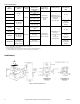
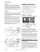
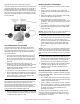
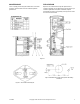
Table Of Contents
- GENERAL INFORMATION
- Options
- Table-1 Model Chart.
- Figure-1 Mounting Dimensions.
- INSTALLATION
- Locating
- Mounting
- One Temperature Thermostats
- 1. The scale on the thermostat represents 30°F (17°C) or 60°F (33°C) span (see page 1) with the desired control point in the center. Each division is equal to 5°F (3°C) for 30°F (17°C) span units and 10°F (6°C) for 60°F (33°C) span units.
- 2. Observe the temperature of the bulb using a test thermometer. Turn the knob of the thermostat to the point on the scale which would correspond to the bulb temperature. Read the branch line pressure. It should be 8 psig ±1 psig (55 kPa ±7 kPa).
- 3. If the pressure is not 8 psig (55 kPa) use a .048" Bristol wrench (TOOL-82) in the calibrating screw and adjust the screw to ...
- 4. When the calibration has been completed, turn the knob to the desired setpoint and remove the gauge, reconnect the branch line and replace the cover.
- 1. The scale on the thermostat represents 30°F (17°C) or 60°F (33°C) span (see page 1) with the desired control point in the center. Each division is equal to 5°F (3°C) for 30°F (17°C) span units and 10°F (6°C) for 60°F (33°C) span units.
- Heating-Cooling Thermostats
- 1. Adjust the supply line pressure for the system to 25 psig (172 kPa).
- 2. Connect a pressure regulator into the supply main between the main and the thermostat at the thermostat location.
- 3. Adjust the regulator to 20 psig (138 kPa); at this supply pressure the thermostat is direct acting.
- 4. Set the dial knob on the thermostat to the bulb temperature setting and observe the branch line control air pressure. This pressure should be 8 psig ±1 psi (55 kPa ±7 kPa).
- 5. If not, adjust the direct acting screw to obtain 8 psig (55 kPa) branch line control pressure using a .048" Bristol wrench (Tool-82).
- 6. Adjust the regulator in the main line to 15 psig (103 kPa). At this supply pressure the temperature is reverse acting.
- 7. Observe the branch line control air pressure. If this pressure is not 8 psig (55 kPa), use a .048" Bristol wrench (TOOL-82) and adjust the reverse acting calibrating screw to obtain an 8 psig (55 kPa) branch line control pressure.
- 8. Recheck calibration by switching the supply pressure between 15 and 20 psig (103 and 138 kPa) several times and observe the control pressure. If it varies from the desired pressure, repeat the calibration procedures.
- 9. Calibration is now complete. Turn the adjusting knob to the desired setpoint. Remove the test gauge and regulator, reconnect the main and branch lines and replace the cover.
- 1. Adjust the supply line pressure for the system to 25 psig (172 kPa).
- Heating-Cooling Low Limit TK-4212-201
- Figure-6

F-12585-8 © Copyright 2009 Schneider Electric All Rights Reserved. 3
INSTALLATION
Locating
The thermostat can be mounted in any position. However, it is
most common to mount the thermostat with the setpoint
adjusting shaft on top. The adjusting mechanism is in the
thermostat on the side opposite from the setpoint knob shaft.
This area should be readily accessible so that the thermostat
can be serviced easily. Locate the bulb in the return air intake
in a position where it will sense representative air
temperatures.
Mounting
If the thermostat is mounted directly to the unit air conditioner,
drill three holes corresponding to the location of the mounting
holes and setpoint shaft in the thermostat. To use bracket, drill
three holes to match any three of the five bracket mounting
holes selected (Figure 1).
Mount the thermostat using the two #10-32 screws, and the
scale plate which indicates the temperature setting. Attach the
knob, positioned so that the pointer indicates the cooler
(CCW) position on the scale. Rotate setpoint to midscale.
Uncoil the capillary tubing and fasten the bulb in the air stream
being controlled as shown in Figures 2 and 3 below. (See
Figures 7 and 8 for duct mounting template and assembly).
Attach 1/4" O.D. plastic tube to “m” (main) and “B” (branch)
fittings by slightly rotating the tubes back and forth and
pushing firmly onto the fitting (see Figure 4).
Figure-2 Mounting TK-2000 Series Bulb.
Figure-3 Mounting TK-4000 Series Bulb.
CONVERSION OF DIRECT ACTING
THERMOSTAT TO REVERSE ACTING
1. Remove direct acting calibration screw complete with
tension nut (Figure 4).
2. Insert screw into threaded hole where reverse acting
screw is shown in Figure 4.
3. Tighten tension nut carefully until it is snug.
Caution: DO NOT overtighten as this will ruin nut.
4. Calibrate per instructions shown below.
Figure-4
THROTTLING RANGE ADJUSTMENT
The throttling range should be set at the lowest value which
will allow the thermostat to control the system without cycling
under normal load conditions. The most satisfactory setting
will vary with the type of control system.
The throttling range is changed by sliding the throttling range
adjustment pivot in the flapper to its proper position (see
Figure 4). Calibration of the thermostat should be checked
after the throttling range has been changed. When making the
throttling range adjustment, care should be taken to prevent
excessive side forces on the flapper lever (see Figure 6).
Caution: In no case should the pivot point be raised when
the adjustment is made (see Figure 6).
CALIBRATION
After the throttling range adjustment is made, the thermostat
should be checked for calibration. As a nominal calibration,
the controlled branch pressure should be 8 psig (55 kPa)
when the setpoint is equal to the bulb temperature, indicated
by a thermometer located near the bulb. In some applications,
a value other than 8 psig (55 kPa) will be required to get the
desired control results. Change the 8 psig (55 kPa)
designation as used in the calibration procedure, should this
be the case.