
User Guide


F-18785-9 © Copyright 2008 TAC All Rights Reserved. 3
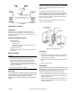
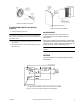
Figure-1 TC-1100 Series Switch Action and Lead
Identification.
PRE-INSTALLATION
Inspection
Inspect the carton for damage. If damaged, notify the
appropriate carrier immediately. If undamaged, open the
carton and inspect the device for obvious damage. Return
damaged products.
Required Installation Items
• Wiring diagrams
• Tools (not provided):
– Volt-ohm meter
– Appropriate screwdriver for mounting screws and
terminal connections
• Appropriate accessories
• Mounting screws, two (2) provided for securing to a 2 x 4
conduit box
INSTALLATION
Caution:
1. Installer must be qualified, experienced technician.
2. Make all connections in accordance with the wiring
diagram, and in accordance with national and local
electrical codes. Class I wiring is required unless all
circuits to contacts are powered from Class II source.
Use
copper conductors only
.
3. Do not exceed ratings of the device.
Mounting
Thermostats require upright mounting on a properly flat
vertical surface. Locate the thermostat where it will be
exposed to unrestricted circulation of air which
represents the average temperature of the controlled
space.
Caution:
Do not locate the thermostat near sources of heat
or cold, such as lamps, motors, sunlight or concealed ducts
or pipes, or where there is a danger of electrocution (i.e.
shower rooms).
The thermostat is designed for service in any normally
encountered human environment. Avoid locations where
excessive vibration, moisture, corrosive fumes or vapors are
present. NEMA Type 1 covers are intended for indoor use
primarily to provide a degree of protection against contact
with the enclosed equipment.
Thermostats with guards that restrict air flow must have
heating or cooling anticipation.
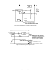
Figure-2 Thermostat Mounting
Procedure
1. Pull all wires.
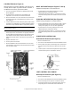
2. Make electrical connections to thermostat. (Typical heat
anticipation and night depression wiring diagrams are
shown in Figures 7 through 9.)
3. Remove thermostat cover and fasten thermostat to box or
wall.
4. Attach thermostat cover.
CHECKOUT
After installing a thermostat, make an initial check of the
switching action. Verify the switch action by listening to
and watching the switch contacts or by using a
voltmeter between the proper sides of the switch.
1. Run the setpoint dial to a temperature above ambient. This
should cause the thermostat to make a circuit between
orange and brown leads.
2. Turn the setpoint dial setting down below ambient. This
should cause the thermostat to make a circuit between
orange and red leads.