
User Guide

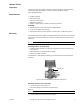
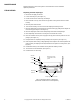
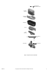
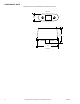


Table Of Contents
- Application
- Features
- Applicable Literature
- Inspect the package for damage. If damaged, notify the appropriate carrier immediately. If undamaged, open the package and inspect the device for obvious damage. Return damaged products.
- The MK-2690 is generally installed in an upright position. When connecting to the control air line the actuator may be swiveled to any convenient position above the center line of the valve body.
- The actuator should be removed from the valve body during valve installation.
- For information on valve linkage assembly, see General Instructions for AV-400 linkage (F-19073).
- When removing the actuator, make sure that the piston is not pulled out of the diaphragm.
- Regular maintenance of the total system is recommended to assure sustained optimum performance.
- 1. Disconnect air supply to actuator.
- 2. Loosen mounting nut. (See Figure-3.)
- 3. Lift the actuator off the valve body and linkage.
- 4. Place actuator on its top, and remove two (2) lower housing screws. Remove lower housing.
- 5. Remove piston from actuator.
- 6. Turn actuator housing over and remove the diaphragm retaining screws.
- 7. Remove diaphragm and its retainer from actuator housing by pulling them straight out from housing. (See Figure-2 and Figure-3.)
- 8. Remove diaphragm retainer from old diaphragm and install new diaphragm.
- 9. Place diaphragm and retainer in housing and secure with two screws.
- 10. Place the actuator housing on its top (open side up) and center the piston on the diaphragm. (See Figure-2.)
- 11. Pull protrusions on diaphragm through mating holes on piston. (See Figure-2.)
- 12. Push the piston down evenly, rolling diaphragm around piston. Be certain to position the piston squarely on diaphragm with equal distances from piston to housing sides. (See Figure-2.)
- 13. Install lower housing to the actuator housing with two retaining screws.
- 14. The actuator is now assembled. (See Figure-1.)
- 15. Install actuator on valve body.
- Figure-2 Positioning Piston in Diaphragm (shown with actuator in the inverted position).
- Figure-3 Exploded View of MK-2690.
- 1. Disconnect air supply to actuator.
- All dimensions in inches (millimeters in brackets). See Figure-4.

F-13893-7 © Copyright 2010 Schneider Electric All Rights Reserved. 3
INSTALLATION
Inspection
Inspect the package for damage. If damaged, notify the appropriate carrier immediately.
If undamaged, open the package and inspect the device for obvious damage.
Return damaged products.
Requirements
• Job piping diagrams
• Tools (not provided):
1-5/8" open-ended wrench
Appropriate screwdriver
• Training: Installer must be a qualified, experienced technician
CAUTION:
• Make all connections in accordance with the piping diagram.
• Do not exceed ratings of the device(s).
• Avoid locations where excessive moisture, corrosive fumes, or vibration is present.
Mounting
The MK-2690 is generally installed in an upright position. When connecting to the control air
line the actuator may be swiveled to any convenient position above the center line of the
valve body.
N O T E
The actuator should be removed from the valve body during valve installation.
Installing Actuator on Valve Body
1. Position actuator assembly over valve stem and spring and secure with mounting nut.
(See Figure-1.)
2. Swivel actuator to convenient position for piping.
3. Connect air supply to actuator.
For information on valve linkage assembly, see General Instructions for AV-400 linkage
(F-19073).
Figure-1 Actuator Assembled to Valve Body with Linkage.
Removing Actuator from Valve Body
1. Loosen mounting nut. (See Figure-1.)
2. Lift actuator straight up until it clears the valve spring.
N O T E
When removing the actuator, make sure that the piston is not pulled out of the diaphragm.
3. Lay the actuator on its top until it is to be installed.
Mounting Nut