
User Guide


10 © Copyright 2008 TAC All Rights Reserved. F-27169-6
4. Orient the actuator mounting bracket on the valve and tighten the hex mounting nut
securely against the bracket using TOOL-37.
5. Insert the crank provided in the actuator cover. Wind the crank two turns
counterclockwise. Press in the turn crank 1/8 turn counterclockwise to lock in position.
6. Rotate the stem extension until the through holes in the stem extension and rack line
up. Insert connecting pin to secure stem extension and tighten jam nut against stem
extension using TOOL-20-1 or a 5
I
16” open end wrench.
B. Apply power to the actuator and check the system operation for heating or cooling output
in response to the control signal.
Installation: Mx51-710x Series Actuator to 1/2" to 2" VB-7xxx Series Valve
Bodies, 2-Way Stem-Up Open
A. Preload the valve to insure proper close-off according to the numbered steps to 10 and
the text below. (Remove power before proceeding.)
1. Locate the steel jam nut that came packaged with the actuator. (Do not re-use the brass
jam nut present on an existing valve.)
2. Screw the nut onto the valve stem all the way as far as it will go (you may need to use
a TOOL-20-1 or a 5/16” open-end wrench). At least 1/2” of the valve stem should
extend above the nut.
3. Thread the stem extension onto the valve stem, making contact with the jam nut. Push
the valve stem to the full down position.
4. Orient the actuator mounting bracket on the valve and tighten the hex mounting nut
securely against the bracket using TOOL-37.
5. Insert the crank provided in the actuator cover. Wind the crank counterclockwise until
the actuator fully extends, then unwind 2 turns and press in and turn crank 1/8 turn
counterclockwise to lock in position.
6. Rotate the stem extension until the through holes in the stem extension and rack
lineup. Insert connecting pin to secure stem extension and tighten jam nut against
stem extension using TOOL-20-1 or a 5
I
16” open end wrench.
B. Apply power to the actuator and check the system operation for heating or cooling output
in response to the control signal.
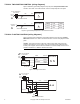
Valve Mounting The valve should be mounted in a weather-protected area, in a location that is within the
ambient temperature limits of the actuator. The installation of the actuator assembly should
provide clearance on all sides to allow for any maintenance that may be needed (see
Figure-10 and Figure-11).
1. Following general piping practices is recommended.
2. Apply pipe sealant sparingly to all but the last two threads of a properly threaded,
reamed, and cleaned pipe. Make sure the pipe chips, scale, etc. do not get into the pipe
since this material may lodge in the valve seat and prevent proper closing and opening
of the valve. The valve must be piped with an inlet and an outlet.
3. Start the joint hand-threading the pipe into the valve. If the thread alignment feels
normal, continue to turn the pipe by hand as far as it will go.
4. Use a pipe wrench to fully tighten the pipe to the valve.
Caution:
Do not over-tighten the pipe, which may cause stripped threads. Avoid twisting
or crushing the valve while tightening the pipe.
5. Insulate only the valve body and associated piping, not the actuator.
6. In chilled or cold water systems where the environment is humid, use a drip pan under
the valve to catch condensate.
Caution:
The TAC DuraDrive linear actuator is designed to effectively support its own
weight. No load or weight should be resting on the actuator, long term damage may occur
to the actuator, mounting connection or the valve.
• Do not insulate the actuator/linkage. Doing so will result in excess heat buildup within
the actuator.