
User Guide

6 © Copyright 2008 TAC All Rights Reserved. F-27169-6
Red
Blk
Com
Hot (+DC)
Line
Volts
(-)
(+)
Yel/Blk
AI
Red
Blk
Com
Hot (+DC)
Yel/Blk
AI
Violet
AO
Violet
AO
MS51-7103-xxx
MS51-7103-xxx
1
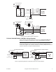
Control Signal
2 to 10 Vdc
24 Vac Transformer
or 20-30 Vdc
2 3
2 3
(-)
(+)
Feedback Signal
2 to 10 Vdc
8
8
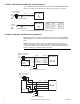
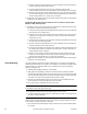
Figure-7a Typical Wiring Diagrams for Proportional Control 24 Vac Models Wired in Parallel
MS51-7103-x40
24 Vac Transformer
or 20-30 Vdc
Red (+20)
Line
Volts
Blue (COM)
Yellow (OLP1)
Typical Controllers
CP-8102
TP-810X
TP-8121
TP-8124
TP-8232
System 8000 controller
requiring external 20 Vdc
power from actuator
1
MS51-7103-x40
2
Red
Blk
Com
Hot (+DC)
24 Vac Transformer
or 20-30 Vdc
Line
Volts
1
Red
Blk
Com
Hot (+DC)
Yel/Blk
Yel/Blk
White/Red
4
24
8
78
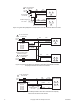
Figure-7b Typical Control Wiring for Two MS51-7103-x40 to System 8000 Controllers
Requiring External 20 Vdc Power from Actuator
MS51-7103-x40
COM
OP1
Typical System
8000 Controllers
CC-8111
CC-8118
CC-8218
CP-8161
CP-8261
24 Vac Transformer
or 20-30 Vdc
Line
V
olts
1
Red
Blk
Com
Hot (+DC)
Yel/Blk
AI
24
Vdc
Feedback Signal
6 to 9 Vdc
(-)
(+)
AO
Violet
78
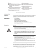
Figure-7c Typical Control Wiring for MS51-7103-x40 to Controllers not Requiring
External 20 Vdc Power from Actuator